Optimization design method for blade root of compound propeller blade

A composite material and propeller blade technology, applied in the direction of calculation, special data processing applications, instruments, etc., can solve the problems that the blade and the propeller hub cannot meet the use requirements, the diameter of the propeller hub is small, and achieve the design method is simple and easy to connect. The effect of firmness and extended service life

Inactive Publication Date: 2013-02-13
HARBIN INST OF TECH
View PDF2 Cites 7 Cited by
  • Summary
  • Abstract
  • Description
  • Claims
  • Application Information

AI Technical Summary

Problems solved by technology

[0004] The present invention solves the blade root connection form designed by the traditional design method. When it is applied to a naval propeller, the profiles between adjacent blades often overlap, and the diameter of the hub is relatively small, so that the blades and the hub cannot meet the requirements. The problem of using requirements, and then put forward an optimal design method of composite propeller blade root

Method used


Image

  • Optimization design method for blade root of compound propeller blade
  • Optimization design method for blade root of compound propeller blade
  • Optimization design method for blade root of compound propeller blade

Examples


specific Embodiment approach 1

[0025] Specific implementation mode one: combine figure 1 and figure 2 To illustrate this embodiment, the specific steps of a composite material propeller blade root design method described in this embodiment are as follows:

[0026] Step 1, increasing the diameter of the top surface and the diameter of the bottom surface of the hub by m times at the same time;

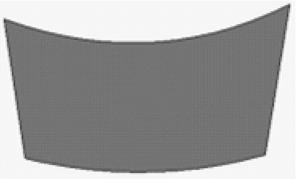
[0027] Step 2, evenly arrange the composite material blades on the enlarged hub, and use the three-dimensional solid configuration software to draw the geometric model of the composite material propeller;

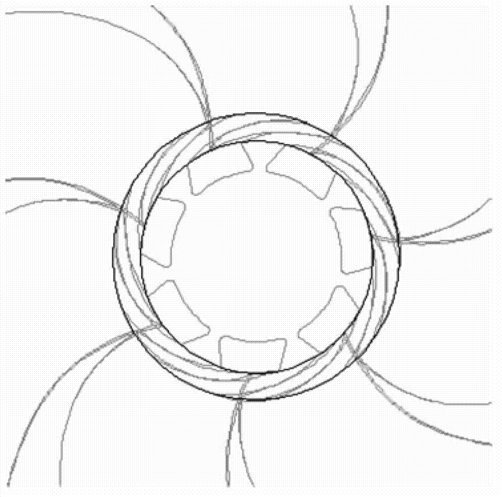
[0028] Step 3. Import the geometric model of the composite material propeller into GAMBIT, the pre-processor of the computational fluid dynamics analysis software, establish the fluid domain, divide the fluid grid, and construct the hydrodynamic model;

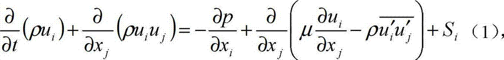
[0029] Step 4. On the basis of the hydrodynamic calculation model that has been constructed, the hydrodynamic performance of the composite propeller is calculat...

specific Embodiment approach 2

[0044] Specific implementation mode two: combination figure 1 and figure 2 To illustrate this embodiment, m=1.05, 1.1, 1.15, 1.2 in Step 1 of a method for optimal design of a composite propeller blade root described in this embodiment. Other components and connections are the same as those in the first embodiment.


PUM


Abstract

The invention relates to an optimization design method for a blade root, in particular to the optimization design method for the blade root of a compound propeller blade, and aims to solve the problem that molded surfaces between adjacent propeller blades are often overlapped when a blade root connection form designed by the conventional design method is applied to a ship propeller, and the diameter of a propeller hub is relatively smaller, so that the propeller blades and the propeller hub cannot meet the use requirements. The optimization design method comprises the following steps: drawing a geometrical model of a compound propeller through a three-dimensional entity configuration software; calculating the hydrodynamic performance of the compound propeller by utilizing an RANS (Reynolds-Averaged Navier-Stokes) equation so as to build a geometrical model of the compound propeller blade with the wedge-shaped blade root; and calculating stress distribution of the propeller blade and the blade root through a finite element analysis software so as to finally finish optimization design of the blade root. The optimization design method is applied to transportation tools such as naval vessels.

Description

technical field [0001] The invention relates to a blade root optimization design method, in particular to a composite material propeller blade root optimization design method. Background technique [0002] As a new type of naval propeller propeller, composite propeller has the characteristics of light weight, high efficiency, low vibration, low noise, seawater corrosion resistance and easy maintenance, and has been increasingly favored by naval propeller designers this year. Generally, a composite material propeller includes a composite material blade and a metal hub, and the blade is fixed on the hub by a blade root. All the dynamic and static loads of the blade are transmitted to the hub through the blade root, so the blade root is the most complicated part of the blade stress state, and it is also the difficulty in the design of the composite material blade. The lower connection is firm, and at the same time strives to be simple in manufacture and convenient in assembly....

Claims


Application Information

Patent Timeline
Patent Type & Authority Applications(China)
IPC IPC(8): G06F17/50
CPCY02T90/00
Inventor 赫晓东洪毅王荣国刘文博矫维成杨帆郝立峰徐忠海张鸿名
Owner HARBIN INST OF TECH
Why Eureka
Try Eureka