Predictive control method of voltage-type PWM (pulse-width modulation) rectifier fixed-frequency model

A technology of model predictive control and rectifier, which is applied to the control of voltage-type PWM rectifier and the field of fixed-frequency model predictive control of voltage-type PWM rectifier. Controller burden and other issues, to achieve the effect of not being easy to design for electromagnetic interference, eliminating high sampling frequency, reducing current ripple and current distortion

Inactive Publication Date: 2013-02-13
GUANGZHOU PANYU TRIO MICROTRONIC
View PDF1 Cites 19 Cited by
  • Summary
  • Abstract
  • Description
  • Claims
  • Application Information

AI Technical Summary

Problems solved by technology

A higher sampling frequency requires the controller to have a fast calculation speed, so it will increase the burden on the controller and increase the system cost; the changing switching frequency is not easy to design the electromagnetic interference filter, which is not conducive to the safe operation of the power device, so in many commercial In the application, a fixed switching frequency control algorithm is generally used

Method used


Image

  • Predictive control method of voltage-type PWM (pulse-width modulation) rectifier fixed-frequency model
  • Predictive control method of voltage-type PWM (pulse-width modulation) rectifier fixed-frequency model
  • Predictive control method of voltage-type PWM (pulse-width modulation) rectifier fixed-frequency model

Examples


Embodiment Construction

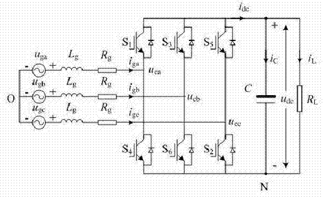
[0014] The present invention will be further described below in conjunction with the accompanying drawings. figure 1 middle, u ga , u gb , u gc is a three-phase voltage source on the AC side, i ga , i gb , i gc is the three-phase AC side current, u ca , u cb , u cc is the three-phase voltage at the input side of the power bridge, u dc is the DC side voltage, L g with R g are the incoming inductance and its equivalent resistance, respectively, C is the DC filter capacitor, O is the midpoint of the grid, i L is the load current, the DC side load is determined by the resistor R L equivalent representation. Define a unipolar binary logic switch function S k , when S k =1( k = a, b, c) for the converter k The upper bridge arm of the phase is opened, and the lower bridge arm is closed; S k =0 means the upper bridge arm is closed and the lower bridge arm is open.

[0015] Under stable conditions, the mathematical model of the PWM rectifier in t...


PUM


Abstract

The invention discloses a predictive control method of a fixed-frequency module of a three-phase PWM (pulse-width modulation) rectifier. The predictive control method is characterized by comprising the following steps of: selecting two voltage vectors and a zero vector adjacent to a power grid voltage position angle to serve as action vectors; taking the acquired power grid voltage and input current values under a two-phase rotary coordinate system and voltage values under the two-phase rotary coordinate system corresponding to the selected two voltage vectors and zero vector to serve as input of a current predictive model to as to acquire a change rate of current on d and q axes; and calculating input of the module by adopting the input current value, the reference value of current on the d and q axes and the change rate of current on the d and q axes as vector duration; inputting the action time of each vector into a modulator; and taking the switch position signal as a switch signal for controlling a power device. According to the predictive control method, the system current ripple and current distortion can be effectively reduced, and the operation performance of the model predictive control system can be reinforced.

Description

[0001] technical field [0002] The invention relates to a control method of a voltage-type PWM rectifier, which belongs to the control field of power electronic power conversion devices, in particular to a fixed-frequency model predictive control method for a voltage-type PWM rectifier. Background technique [0003] Model predictive control is a control algorithm that predicts its future response based on the model of the controlled object. The algorithm includes a value function defined in terms of control objectives. By minimizing this cost function, the algorithm predicts the most effective voltage vector in each sampling period and uses it as the action vector in the next sampling period. Because a large number of calculations are required in each sampling period, model predictive control is generally used in occasions that do not require high system response speed. With the dramatic increase in the calculation speed of microprocessors, the model predictive control s...

Claims


Application Information

Patent Timeline
Patent Type & Authority Applications(China)
IPC IPC(8): H02M7/219
Inventor 王萌施艳艳
Owner GUANGZHOU PANYU TRIO MICROTRONIC
Why Eureka
Try Eureka