
Sampling clock synchronizing method and system

A sampling clock synchronization, sampling pulse technology, applied in time division multiplexing systems, electrical components, multiplexing communications, etc., can solve the problems of error accumulation, hardware requirements and high cost

Active Publication Date: 2013-02-13
AEROSPACE SCI & IND SHENZHEN GROUP
View PDF8 Cites 25 Cited by
  • Summary
  • Abstract
  • Description
  • Claims
  • Application Information

AI Technical Summary

Problems solved by technology

[0005] The purpose of the embodiments of the present invention is to provide a method for synchronizing sampling clocks, which aims to solve the problems of error accumulation, hardware requirements and high cost of traditional sampling pulse clocks

Method used


Image

  • Sampling clock synchronizing method and system
  • Sampling clock synchronizing method and system
  • Sampling clock synchronizing method and system

Examples


Embodiment Construction

[0029] In order to make the technical problems, technical solutions and beneficial effects to be solved by the present invention clearer, the present invention will be further described in detail below in conjunction with the accompanying drawings and embodiments. It should be understood that the specific embodiments described here are only used to explain the present invention, not to limit the present invention.

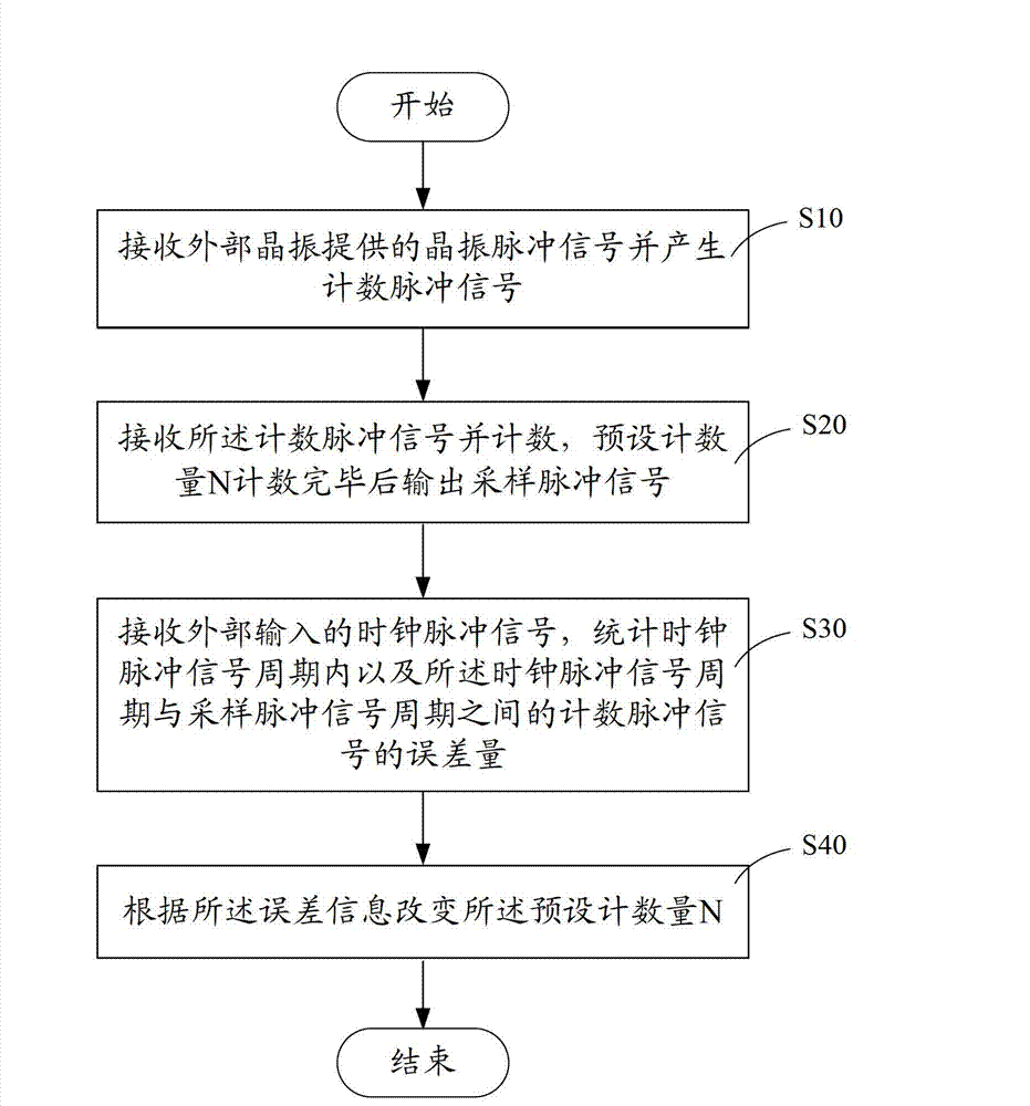
[0030] Such as image 3 As shown, it is a flow chart of a method for realizing sampling clock synchronization in a preferred embodiment. The method for realizing sampling clock synchronization is realized based on a programmable gate circuit integrated chip. In this embodiment, it is mainly implemented in CPLD (Complex Programmable Logic Device, complex programmable logic device) logic chip uses logic circuit design to realize corresponding clock pulse signal comparison, sampling pulse generation, sampling pulse adjustment and other functions, and finally realizes ...


PUM


Abstract

The invention is applicable to the field of industrial control and provides a sampling clock synchronizing method. The method comprises the following steps of: receiving crystal oscillator pulse signals provided by an external crystal oscillator and generating count pulse signals; receiving the count pulse signals for counting, and outputting sampling pulse signals after the counting of a preset counting quantity N is finished; receiving externally-input time pulse signals, and counting errors of the count pulse signals within a clock pulse signal period and between the clock pulse signal period and a sampling pulse signal period; and changing the preset counting quantity N according to the errors. By adopting the external stable clock pulse signals, the sampling clock synchronizing method can be used for adjusting the inherent errors of the crystal oscillator pulse singles and the errors caused by the factor that the count pulse signals trigger the sampling pulse signals under the influence of temperature change of work environments, so that the errors of crystal oscillator frequency can be reduced to the greatest extent, the effect of the accumulated errors on a sampling pulse can be eliminated, and the error accumulation of a sampling pulse clock is overcome.

Description

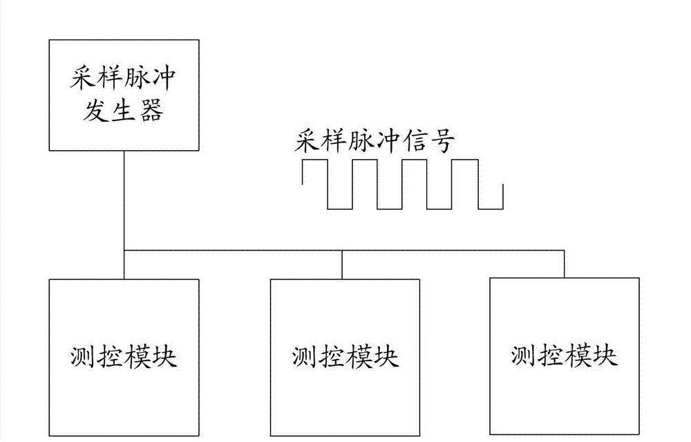
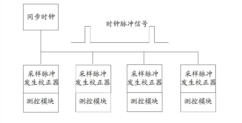
technical field [0001] The invention belongs to the field of industrial control, in particular to a method and system for realizing sampling clock synchronization. Background technique [0002] In the construction of the smart grid, many places have very high requirements for the synchronization of remote data acquisition, such as between the merging units in the digital substation, and between the PMU (Phasor Measurement Unit, phasor measurement unit) in the wide-area vector measurement system , Fault recording devices between different substations, etc. [0003] At present, there are generally two ways to achieve data synchronization between acquisition devices: one is to use the same sampling pulse among multiple devices, and the same sampling pulse is connected to each acquisition device through hardware connection, so that the sampling of each device is synchronized, such as figure 1 shown; the other is through a unified clock pulse signal (such as GPS clock, Beidou cl...

Claims


Application Information

Patent Timeline
IPC IPC(8): H04J3/06
Inventor 赖晓明
Owner AEROSPACE SCI & IND SHENZHEN GROUP
Learn More