
Multi-mode modulation microwave signal generation method

A technology of microwave signal and generation method, applied in the field of communication, can solve the problems that signal storage is difficult to achieve coherent storage and effective modulation output, cannot achieve microwave signal integrity, coherent acquisition, copying, and output, etc., and achieves high practical value. , the effect of high accuracy and fast processing speed

Inactive Publication Date: 2013-02-13
中国人民解放军济南军区72465部队
View PDF5 Cites 2 Cited by
  • Summary
  • Abstract
  • Description
  • Claims
  • Application Information

AI Technical Summary

Problems solved by technology

[0003] At this stage, most of the research on the signal generation form focuses on the research on the signal frequency, including frequency hopping, spread spectrum signals, or increasing the complexity of the signal content during signal encoding, and enhancing the application of pseudo-random signals. The memory stores the digital signal waveform, and the controller controls the output of different modulated digital waveforms to change the signal generator of the signal modulation mode. The device has not been involved
Moreover, the traditional signal storage is difficult to achieve the coherent storage and effective modulation output required by modern testing and communication, and cannot realize the integrity, coherent acquisition, copying and output of the received microwave signal

Method used


Image

  • Multi-mode modulation microwave signal generation method

Examples


Embodiment 1

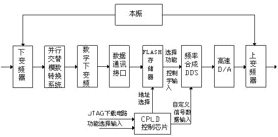
[0018] Roughly measure the frequency of the received signal, tune the local oscillator frequency, and pass the received RF signal and local oscillator signal through the down converter for quadrature mixing and filtering. The analog-to-digital conversion is carried out on the microwave signal output by the frequency mixing by an alternate parallel analog-to-digital conversion system, and converted into a digital signal. The digital signal after the analog-to-digital conversion is down-converted by the digital down-converter, and the intermediate frequency signal output by the A / D conversion is moved to the baseband, and then the channel extraction is completed through extraction and filtering. The processed digital signal is stored in the FLASH memory, and the digital signal control word is sent to the frequency synthesis chip when the signal needs to be generated. The memory outputs different frequency control words to control the DDS chip to output signals in different modul...

Embodiment 2

[0020] Roughly measure the frequency of the received signal, tune the local oscillator frequency, and pass the received RF signal and local oscillator signal through the down converter for quadrature mixing and filtering. The analog-to-digital conversion is carried out on the microwave signal output by the frequency mixing by an alternate parallel analog-to-digital conversion system, and converted into a digital signal. The digital signal after the analog-to-digital conversion is down-converted by the digital down-converter, and the intermediate frequency signal output by the A / D conversion is moved to the baseband, and then the channel extraction is completed through extraction and filtering. The multi-mode signal modulation signal control word is pre-stored in the FLASH memory, and the memory address is changed through the CPLD control chip to make it output different control words to control the DDS chip to output different modulation mode signals, realizing rapid and contin...


PUM


Abstract

The invention relates to a multi-mode modulation microwave signal generation method. The invention adopts the technical scheme that the method comprises the following steps of: controlling a down-converter by tuning a local oscillator to orthogonally mix a radio frequency signal and a local oscillator signal, which are received and required to be stored and coherently transmitted; converting a processed microwave signal into a high-speed digital signal through an alternate parallel analog-to-digital conversion system; and performing down-conversion on a high-frequency digital signal by using a digital down-converter, storing the high-frequency digital signal into a flash memory, and then analyzing and converting the signal. By adoption of the multi-mode modulation microwave signal generation method, the microwave signal can be quickly and accurately converted, stored, modulated and then coherently output, so the microwave signal can be stored and reproduced, different modulation modes can be quickly switched in continuous time, and the method is high in operation efficiency, high in processing speed, high in accuracy and high in practicability.

Description

technical field [0001] The invention belongs to the technical field of communication, and in particular relates to a method for generating a microwave signal. Background technique [0002] Signal sources or signal generating equipment are widely used in communication systems, performance testing and other fields, as well as jamming equipment for weaponry systems and analog signal sources for anti-jamming training. With the rapid development of informatization and electronicization in today's society, modern test equipment and communication equipment are constantly highly integrated, and the functions need to be continuously enhanced to generate different test signals to meet different needs. It is necessary to be able to generate radio frequency signals in different signal forms. In communication and detection equipment, the signal source is the basis of the whole system, so it is particularly important for the construction of the signal. [0003] At this stage, most of the...

Claims


Application Information

Patent Timeline
Patent Type & Authority Applications(China)
IPC IPC(8): H04L27/00H04L25/03H03D7/16
Inventor 刘静薛兰柱石晓原姜恒辛军高彬崔广志胡向顺查连中孟祥成路晖
Owner 中国人民解放军济南军区72465部队
Learn More