
Shaping rack

A technology of bench and positioning groove, which is applied in the direction of ceramic forming machines and manufacturing tools, can solve the problems of difficult steel bar spacing and protective layer thickness, long inspection and verification time, and low operation efficiency, so as to shorten the construction period and promote good promotion The effect of convenient use value and quality inspection

Inactive Publication Date: 2013-02-20
GANSU ROAD & BRIDGE CONSTR GROUP
View PDF9 Cites 4 Cited by
  • Summary
  • Abstract
  • Description
  • Claims
  • Application Information

AI Technical Summary

Problems solved by technology

The installation and processing of steel bars for beams and slabs is an important process in the prefabrication of beams and slabs. The traditional steel skeleton binding is directly constructed on the prefabricated base of beams and slabs. It is difficult to ensure the spacing of steel bars and the thickness of the protective layer. At the same time, the operation efficiency is low and the labor intensity is high. , Inspection and verification time is long

Method used


Image

  • Shaping rack
  • Shaping rack

Examples


Embodiment Construction

[0013] A shaping stand of the present invention will be described in detail below in conjunction with the accompanying drawings.

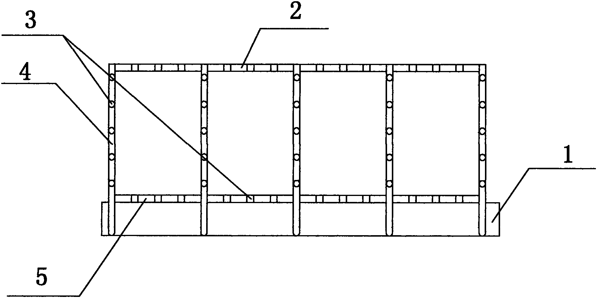
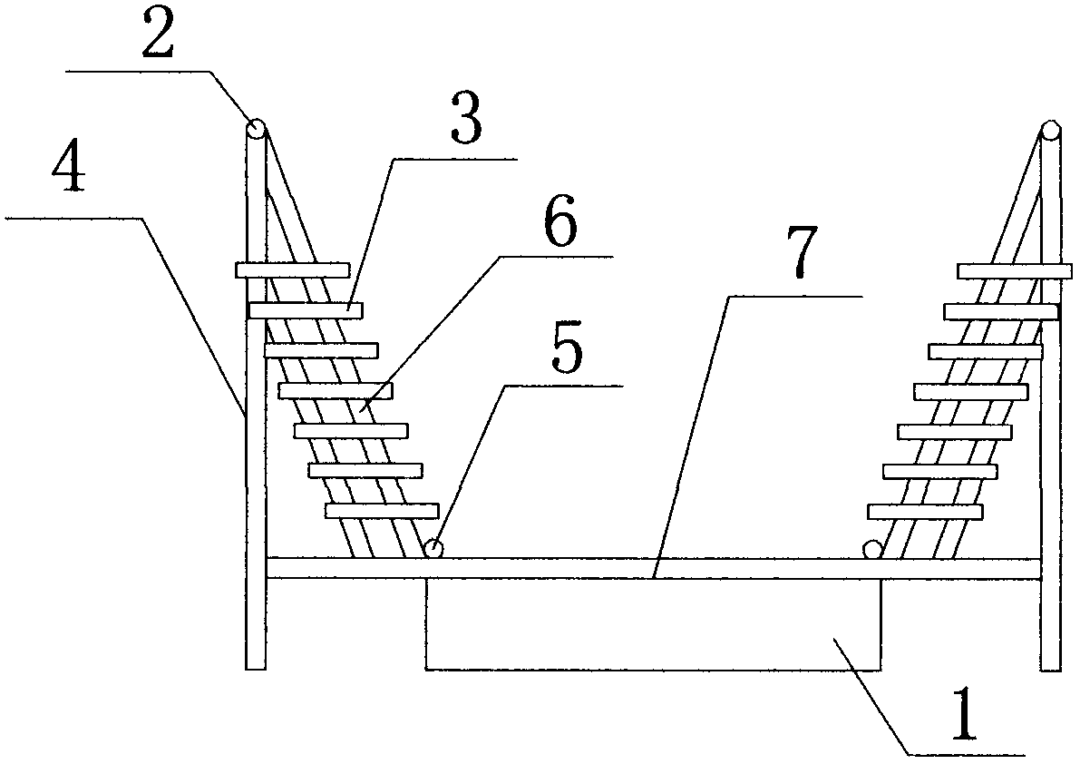
[0014] as attached figure 1 , figure 2 As shown, the above-described shaped bench includes a bench base 1, an integral frame arranged on the bench base 1, and a steel bar positioning groove 3 arranged on the integral frame. The horizontal frame frame 6 and the horizontal frame bottom frame 7 on the frame base 1, two upper vertical frames 2, two lower vertical frames 5 vertically arranged on both sides of the frame base 1, the two lower vertical frames 5 are connected to all The bottom frame of the horizontal frame 7, the two ends of the bottom frame of the horizontal frame 7 extend out of the platform base 1 and are vertically connected with the vertical rod 4, and the top of the vertical rod 4 on each side of the platform base 1 is connected with an upper vertical frame 2, A horizontal frame frame 6 is arranged between the upper vertical frame ...


PUM

PropertyMeasurementUnit
heightaaaaaaaaaa

Abstract

The invention provides a shaping rack which comprises a rack base, an integral framework arranged on the rack base, and steel bar positioning grooves arranged on the integral framework, wherein the integral frame comprises a plurality of transverse frames transversely arranged on the rack base, two upper longitudinal frames, and two lower longitudinal frames longitudinally arranged on two lateral sides of the rack base; the two lower longitudinal frames are connected with all the transverse frames; both ends of the transverse frames protrude out of the rack base and are perpendicularly connected with upright poles; the top of the upright pole at each side of the rack base is connected with one upper longitudinal frame; a border frame is arranged between the upper longitudinal frame and the lower longitudinal frame at each side; and the steel bar positioning grooves are formed in the transverse frames and the border frames in an equidistant manner. Compared with the prior art, the shaping rack has the beneficial effects that the interval and the size of a steel bar can be precisely positioned, the bundling speed is fast, checking is convenient, few labors are used, protective layer cushion blocks are mounted integrally and spaced uniformly, the steel bar framework manufacturing quality is ensured, the construction cycle is effectively shortened, and the cost is saved.

Description

technical field [0001] The invention relates to an auxiliary tool for road and bridge construction, in particular to a steel bar shaping platform with fast binding speed, less labor force and effectively shortened construction period. Background technique [0002] The prefabrication of beams and slabs in highway engineering construction widely implements the construction of "centralization, standardization, and factoryization". How to effectively shorten the prefabrication period of beams and slabs, improve the quality of beams and slabs, and reduce construction costs has become the main topic of project management. The installation and processing of steel bars for beams and slabs is an important process in the prefabrication of beams and slabs. The traditional steel skeleton binding is directly constructed on the prefabricated base of beams and slabs. It is difficult to ensure the spacing of steel bars and the thickness of the protective layer. At the same time, the operatio...

Claims


Application Information

Patent Timeline
Patent Type & Authority Applications(China)
IPC IPC(8): B28B23/18
Inventor 祁建福任文宏张伟利张晓张剑惠鹏嘉
Owner GANSU ROAD & BRIDGE CONSTR GROUP
Learn More