Method for manufacturing metal and plastic composite casing

A production method and metal shell technology, applied in the direction of coating, etc., can solve the problems of unsatisfactory appearance, poor bonding firmness, and difficulty in releasing the buckle structure, so as to maintain gloss and texture, and good tensile resistance Effect

Active Publication Date: 2013-02-20
SHENZHEN C&D ELECTRONICS
View PDF5 Cites 10 Cited by
  • Summary
  • Abstract
  • Description
  • Claims
  • Application Information

AI Technical Summary

Problems solved by technology

[0004] The locking method of the face shell generally cannot be locked by screws, but if the overall buckle is used for locking, the buckle structure will be difficult to release the mold, and the mold will have the risk of not being mass-producible and scrapped;
[0005] For electronic products with pure metal shells, it is difficult to design anti-static hardware on the hardware, and it will increase the cost;
[0006] If the metal shell (especially the aluminum alloy shell) is formed by die-casting, the oxidation treatment on the surface of the workpiece is prone to yin and yang, and it is difficult to achieve the visual effect of the metal color. The color is dark and the appearance is not satisfactory.
[0007] In view of the above reasons, people began to look for a composite shell made of "metal + plastic". As a result, a composite shell that was glued between a stamped metal thin shell and a plastic shell came into being, but this The Achilles’ heel of the composite shell is the poor bonding firmness. Usually, it is difficult to withstand the pull-out force test with a strength of more than 50 N and separate, and the timeliness is poor, and the composite shell will peel off over time.

Method used


Image

  • Method for manufacturing metal and plastic composite casing
  • Method for manufacturing metal and plastic composite casing

Examples


Embodiment Construction

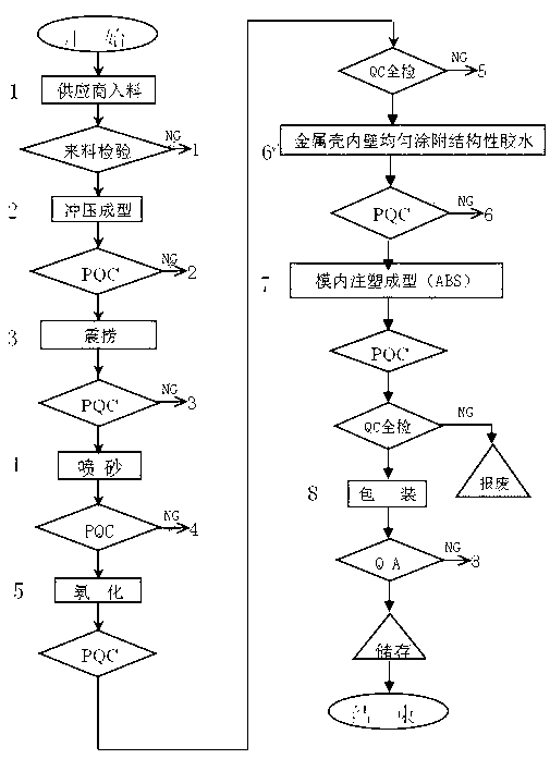
[0041] The present invention will be further described below in conjunction with the accompanying drawings.

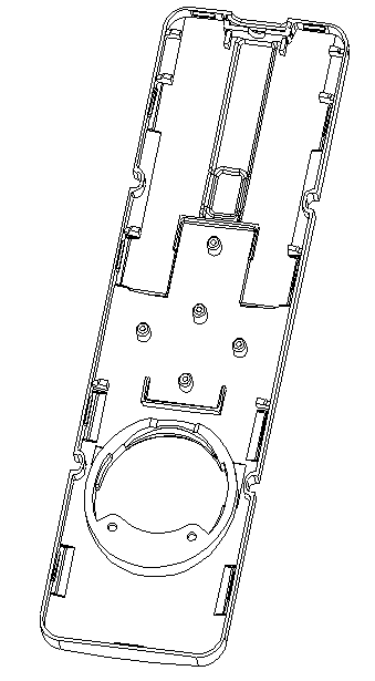
[0042] The invention is mainly applicable to the casing processing of electronic products such as mobile phones, cordless phones and remote controllers.

[0043] The "in-mold injection molding" technology has solved various technical problems in the background technology very well: it refers to that in the process of shell processing, the inner wall of the finished metal shell after stamping and surface treatment is uniformly sprayed with a structural After adding additives, put it in the injection mold, and then inject a layer of plastic material according to the process conditions of injection molding, so that the metal shell and the plastic are tightly combined and inseparable. Usually, it can pass the pull-out force test of more than 80 Newtons .

[0044] working principle:

[0045] During the processing of the shell, the inner wall of the stamped and surface-tr...


PUM

PropertyMeasurementUnit
thicknessaaaaaaaaaa

Abstract

The invention provides a method for manufacturing a metal and plastic composite casing. The method comprises the following steps of 1, spraying plastic onto a finished metal casing subjected to stamping forming and surface processing; and 2, injection moulding in a mould: performing injection molding on the metal casing subjected to plastic spraying within 12 hours, wherein, when the injection molding is processed, the metal casing is firstly placed into a mould cavity of the injection mould to be fixed, the casing is in interference fit with the mould cavity, and acrylonitrile butadiene styrene (ABS) and poly carbonate (PC) are injected into the mould. The stamped metal and plastic injection moulding composite casing manufactured by the method has good stretching resistance, and a metal layer and a plastic layer can not be stripped when the stamped metal and plastic injection moulding composite casing pulls 80 Newton through a single point. In the aspect of the appearance, luster and texture of metal materials can be remained well, and in the aspect of the internal structure, all features of plastic materials can be remained. An upper casing and a lower casing can be locked through button placement conveniently, and outside electronic static discharge (ESD) can be shielded well.

Description

technical field [0001] The invention relates to a manufacturing method of a conforming shell, in particular to a manufacturing method of a stamped metal shell + plastic injection molding composite shell. Background technique [0002] For a long time, the casings of household consumer electronic products such as mobile phones, cordless phones and remote controls are generally made of plastic injection molding and then surface sprayed with silk screen laser engraving or electroplating. In addition to cost considerations, the main The molding process of plastic materials is simple and has good flexibility. It is easier to realize the buckle locking method between the shells in the mold, and the appearance is beautiful and generous, but no matter how good the surface treatment is, it cannot withstand it anyway. Considering the time, the common phenomenon is that after a period of use, the coating or oil injection layer falls off, and the bottom of the plastic material is exposed...

Claims


Application Information

Patent Timeline
Patent Type & Authority Applications(China)
IPC IPC(8): B29C45/14B29C45/17B29B11/00
Inventor 李方举
Owner SHENZHEN C&D ELECTRONICS
Why Eureka
Try Eureka