Device for downward conveying concrete

A technology for concrete and pumping pipes, which is applied in construction, infrastructure engineering, etc., can solve the problems of concrete segregation, easy pipe blockage, and difficult pipe blockage, etc., and achieve the effect of increasing its own gravity and friction, and increasing concrete resistance

Active Publication Date: 2015-07-08
CHINA RAILWAY 23RD CONSTR BUREAU LTD +1
View PDF6 Cites 0 Cited by
  • Summary
  • Abstract
  • Description
  • Claims
  • Application Information

AI Technical Summary

Problems solved by technology

[0002] The conventional method of pumping concrete for pile foundation filling is to use topography from bottom to top or terrain with small level difference, which is not easy to block pipes. However, due to the geographical conditions of the construction site, the distance between some pile foundations and pump trucks is high. The difference is large, and the concrete can only be transported from top to bottom. During the construction process, due to the large height difference, the linear pump pipe is too long and the problem of its own pumping pressure, there are great construction difficulties and quality risks. The reasons are as follows:
[0003] 1. When conveying concrete downward, the concrete in the conveying pipe is not easy to maintain a continuous state of movement, that is, during the pumping process, the speed of the concrete falling by itself exceeds the pumping speed of the conveying pump, which will cause the concrete to flow by itself and form segregation, which is prone to blockage management situation;
[0004] 2. During the process of stopping the pump, the concrete will flow by itself and form an air column in the pipeline. The air column is equivalent to a section of spring. After restarting the pumping, the air column will absorb the pumping pressure, and it is easy to get stuck due to the pump not moving.

Method used


Image

  • Device for downward conveying concrete
  • Device for downward conveying concrete

Examples


Embodiment 1

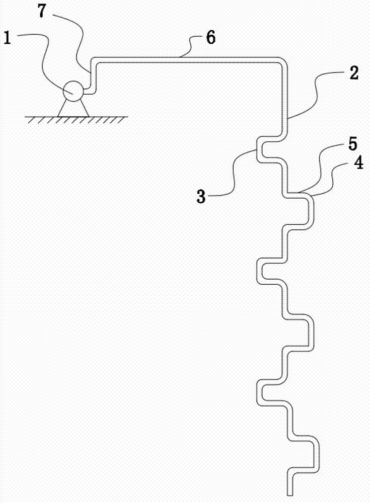
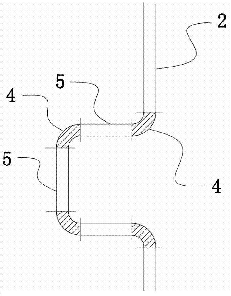
[0025] Such as figure 1 and figure 2 As shown, the present embodiment is a device for conveying concrete downwards, including a pump truck 1 arranged on a high floor, the pump port of the pump truck 1 is connected with a pumping pipe 2 extending vertically downwards, through which the pumping pipe 1 2 and the pump truck 1 realize pumping of concrete. The pumping pipe 2 is provided with a detour 3 . The inlet and outlet ends of the detour 3 are coaxially arranged on the pumping pipe 2 . Lateral extension, that is, the circuitous pipeline extends laterally. By setting the circuitous pipeline extending laterally along the pumping tube 2, the flow direction of the pumping tube 2 that originally only extends downward in the vertical direction is changed to enhance the pumping pressure and The friction between the concrete and the inner wall of the pipeline reduces the flow rate due to the gravity of the concrete itself, thus avoiding the concrete falling with its own weight with...

Embodiment 2

[0029] Such as figure 1 As shown, in this embodiment, a horizontal connecting pipe 6 is arranged between the pump port and the pumping pipe 2, the inlet end of the horizontal connecting pipe 6 is connected to the pump port, and the inlet end of the horizontal connecting pipe 6 is higher than The pump port, optimally, the inlet end of the horizontal connecting pipe 6 is 1m to 2m higher than the pump port, and the concrete is in an upward trend during pumping, which increases the self-gravity and friction of the concrete in the front section.

[0030] In order to increase the self-gravity and friction of the concrete in the front section, a vertical connecting pipe 7 is arranged between the inlet end of the horizontal connecting pipe 6 and the pump port, and a vertical connecting pipe 7 is provided at both ends of the vertical connecting pipe 7 for connecting the pump port. , The right-angled elbow 4 of the horizontal connecting pipe 6, through this connection method, the concr...


PUM


Abstract

The invention discloses a for downward conveying concrete, comprising a pump truck arranged on a high-level terrace, wherein a pump opening of the pump truck is connected with a pumping pipe which extends vertically and downwards; the pumping pipe is provided with a detoured bent pipe; an inlet end and an outlet end of the detoured bent pipe are coaxially arranged on the pumping pipe; the detoured bent pipe extends toward the lateral direction of the pumping pipe; and the detoured bent pipe which extends toward the lateral direction of the pumping pipe is arranged so that the previous flowing direction of the pumping pipe which extends downwards in the vertical direction is changed; and therefore, concrete is prevented from falling down without resistance along with the self weight, the concrete resistance is enhanced, and the flowing speed of the concrete in the pipe is prevented from being too fast to be separated and leaked.

Description

technical field [0001] The invention relates to a device for conveying concrete, in particular to a device for conveying concrete downward. Background technique [0002] The conventional method of pumping concrete for pile foundation filling is to use the topography from bottom to top or the terrain with small level difference, which is not easy to block the pipe, but due to the geographical conditions of the construction site, the distance between some pile foundations and the pump truck is high. The difference is large, and the concrete can only be transported from top to bottom. During the construction process, due to the large height difference, the long linear pump pipe and the problem of its own pumping pressure, there are great construction difficulties and quality risks. The reasons are as follows: [0003] 1. When the concrete is conveyed downward, the concrete in the conveying pipe is not easy to maintain a continuous state of movement, that is, during the pumping...

Claims


Application Information

Patent Timeline
Patent Type & Authority Patents(China)
IPC IPC(8): E02D15/04
Inventor 孙亚峰王家新陈幼林刘旭生范金生符运超赵勇刘延龙王瑞萍郑邦友
Owner CHINA RAILWAY 23RD CONSTR BUREAU LTD
Why Eureka
Try Eureka