Eureka AIR delivers breakthrough ideas for toughest innovation challenges, trusted by R&D personnel around the world.

Method for assembling LED (Light-Emitting Diode) and light guide plate and backlight module

A technology of backlight module and assembly method, which is applied in the field of backlight module, can solve the problems such as the variation of the width and size of the LED groove, the easy formation of bright spots, the difficulty of ensuring the parallelism, etc., so as to improve the assembly accuracy, reduce the size difference, and ensure uniformity degree of effect

Inactive Publication Date: 2013-02-20
AU OPTRONICS (XIAMEN) CORP +1
View PDF0 Cites 5 Cited by
  • Summary
  • Abstract
  • Description
  • Claims
  • Application Information

AI Technical Summary

Problems solved by technology

In this way, the width of the LED groove is easily changed due to assembly displacement
In addition, considering the machine precision and process of the flexible circuit board manufacturer, it is difficult to guarantee the parallelism of the LEDs on the FPC.
Furthermore, the LED and FPC are rigidly connected. In order to facilitate assembly and prevent interference, the gap between the outer frame and the LED must be greater than 0.3mm, which will cause poor uniformity and easy formation of hot spots. poor optical properties

Method used


Image

  • Method for assembling LED (Light-Emitting Diode) and light guide plate and backlight module
  • Method for assembling LED (Light-Emitting Diode) and light guide plate and backlight module
  • Method for assembling LED (Light-Emitting Diode) and light guide plate and backlight module

Examples


Embodiment Construction

[0027] In order to make the technical content disclosed in this application more detailed and complete, reference may be made to the drawings and the following various specific embodiments of the present invention, and the same symbols in the drawings represent the same or similar components. However, those skilled in the art should understand that the examples provided below are not intended to limit the scope of the present invention. In addition, the drawings are only for schematic illustration and are not drawn according to their original scale.

[0028] The specific implementation manners of various aspects of the present invention will be further described in detail below with reference to the accompanying drawings.

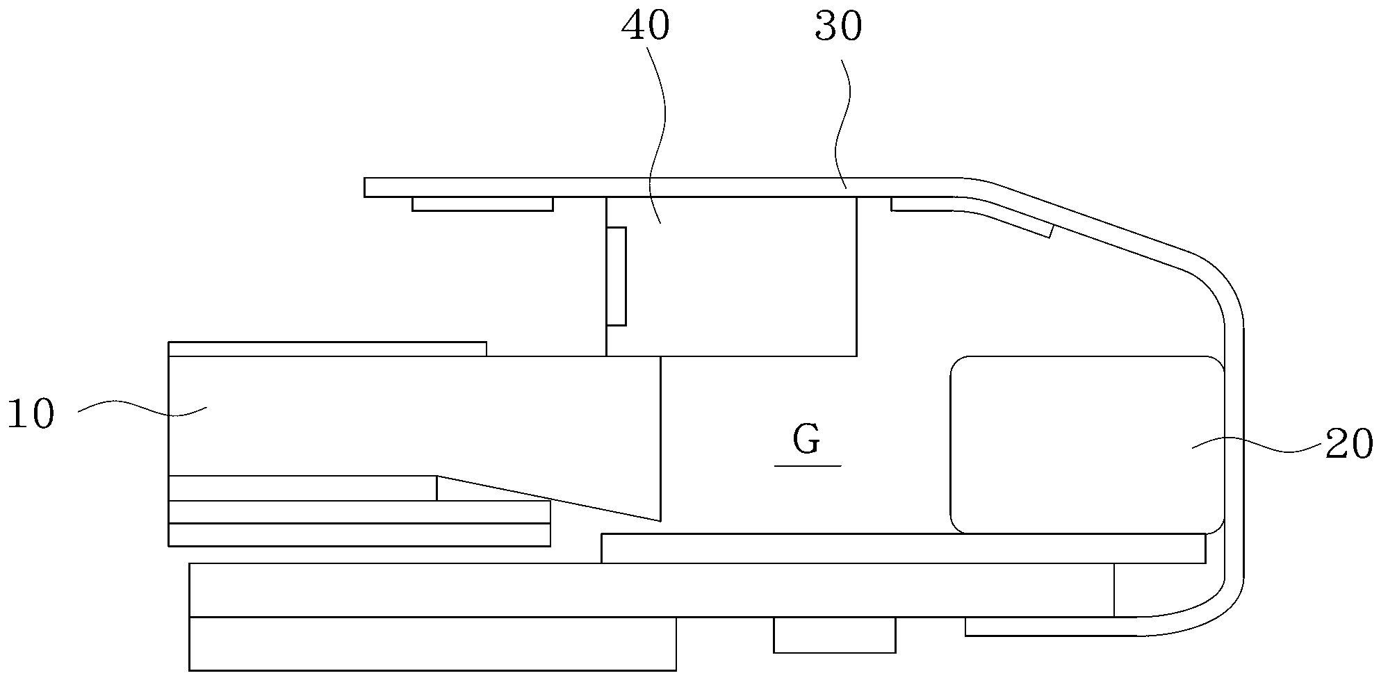
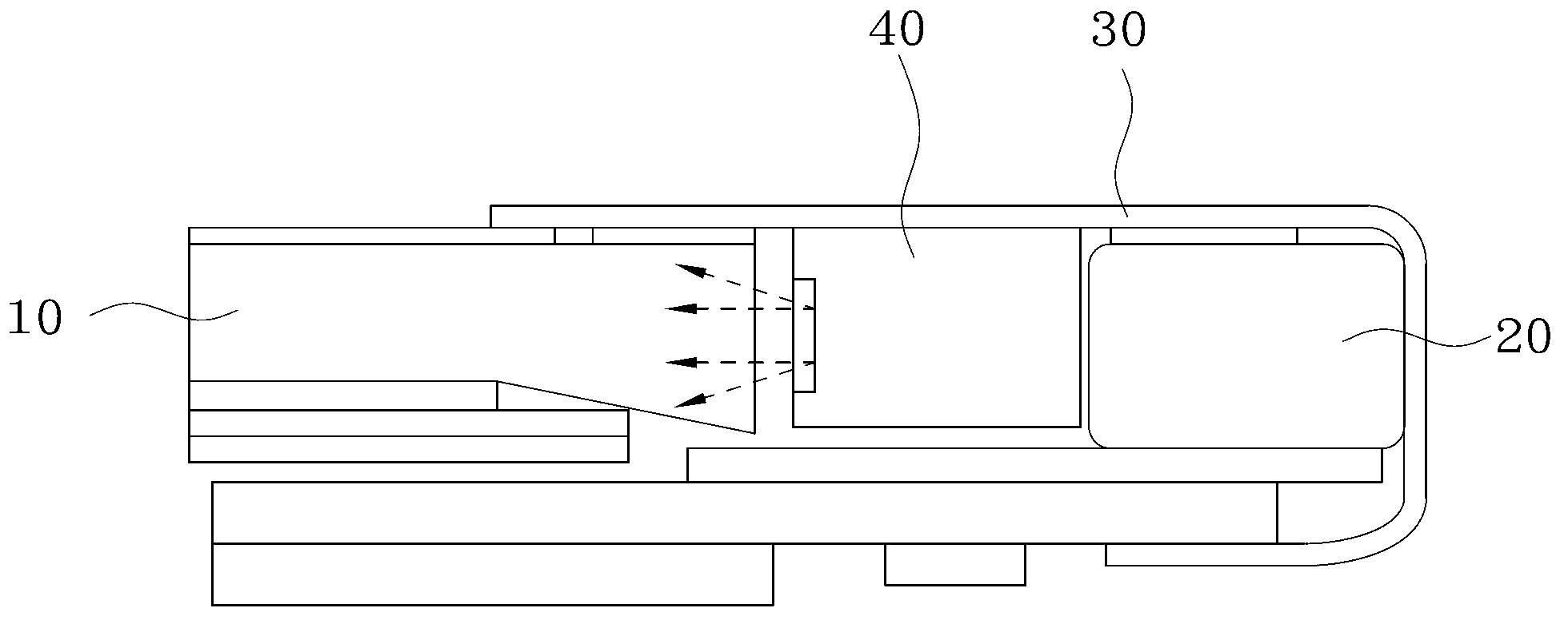
[0029] Figure 1A A schematic diagram showing the interference between the LED light source and the light guide plate when the LED light source and the light guide plate in the prior art are assembled.

[0030] As mentioned above, when assembling the LED l...


PUM


Abstract

The invention provides a method for assembling an LED (Light-Emitting Diode) and a light guide plate and a backlight module. The backlight module comprises a plurality of LEDs, a light guide plate and a flexible circuit, wherein the light guide plate comprises a plurality of first grooves and a plurality of second grooves which are arranged in a staggered manner; the flexible circuit comprises a plurality of containing parts and a plurality of connecting parts; each containing part is arranged in the corresponding first groove; and each connecting part is located in the corresponding second groove. The connecting parts of the flexible circuit are located between the adjacent two containing parts; and the adjacent LEDs are electrically connected in series by the connecting parts. With the adoption of the method disclosed by the invention, the plurality of first grooves and the plurality of second grooves are formed on the light guide plate by adopting a mould direct molding manner; the containing parts are placed into the first grooves and the connecting parts are placed into the second grooves; and the adjacent two LEDs are electrically connected in series by the connecting parts so that the parallelism degree of an LED lamp can be guaranteed, the size difference of different LED grooves is reduced and the assembling precision is improved.

Description

technical field [0001] The present invention relates to a backlight module, in particular to an assembly method for an LED (Light Emitting Diode, light emitting diode) and a light guide plate and a backlight module produced by the assembly method. Background technique [0002] With the continuous improvement of LED backlight technology and performance, the research and development of LED backlight technology for liquid crystal display equipment is also becoming increasingly active. In short, LED is a low-voltage working device, which has the advantages of low-voltage start-up, easy control of working current, good operability, good shock resistance, long service life, wide color gamut, and no harmful substances such as mercury. Therefore, LED It is an ideal light-emitting device as a backlight. Compared with the traditional CCFL (Cold Cathode Fluorescent Lamp, Cold Cathode Fluorescent Lamp) backlight, the LED backlight has lower power consumption, less heat generation, and ...

Claims


Application Information

Patent Timeline
IPC IPC(8): F21S8/00F21V19/00F21Y101/02F21Y115/10
Inventor 黄栽
Owner AU OPTRONICS (XIAMEN) CORP
Why Eureka
Eureka Blog
Learn More