
Monocular vision and binocular vision switching device for small robot

A technology of monocular vision and binocular vision, applied in the field of robot vision, can solve problems such as troublesome installation and maintenance, large weight and volume, troublesome image processing, etc., and achieve good reconstruction effect, wide application and sensitive movement

Inactive Publication Date: 2013-02-20
NORTHWESTERN POLYTECHNICAL UNIV
View PDF7 Cites 11 Cited by
  • Summary
  • Abstract
  • Description
  • Claims
  • Application Information

AI Technical Summary

Problems solved by technology

2. Match the same feature points in different images through multiple images from multiple viewpoints, and use these matching constraints to obtain spatial 3D point coordinate information, thereby realizing 3D reconstruction, which can realize camera self-calibration in the reconstruction process, and can meet large-scale scenes The demand for 3D reconstruction, and the reconstruction effect is better in the case of rich image resources; the disadvantage is that the calculation amount is relatively large, and the reconstruction time is long
But it has the following disadvantages: 1. The image formed by the object and its image overlaps, which brings trouble to the later image processing; 2. When the placement angle of the two sets of mirrors is changed, it is easy to cause the increase of the baseline distance and cause Increase the size of the stereo vision system; 3. The baseline distance is small and the measurement accuracy is low
This mechanism uses two cameras, which is costly and troublesome to install and maintain. At the same time, due to its large weight and volume, it cannot be used on small robots.

Method used


Image

  • Monocular vision and binocular vision switching device for small robot
  • Monocular vision and binocular vision switching device for small robot
  • Monocular vision and binocular vision switching device for small robot

Examples


Embodiment Construction

[0029] Describe the present invention below in conjunction with specific embodiment:

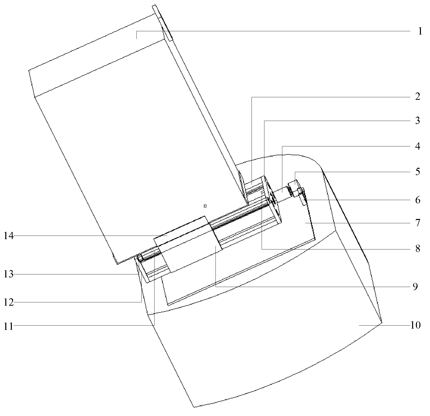
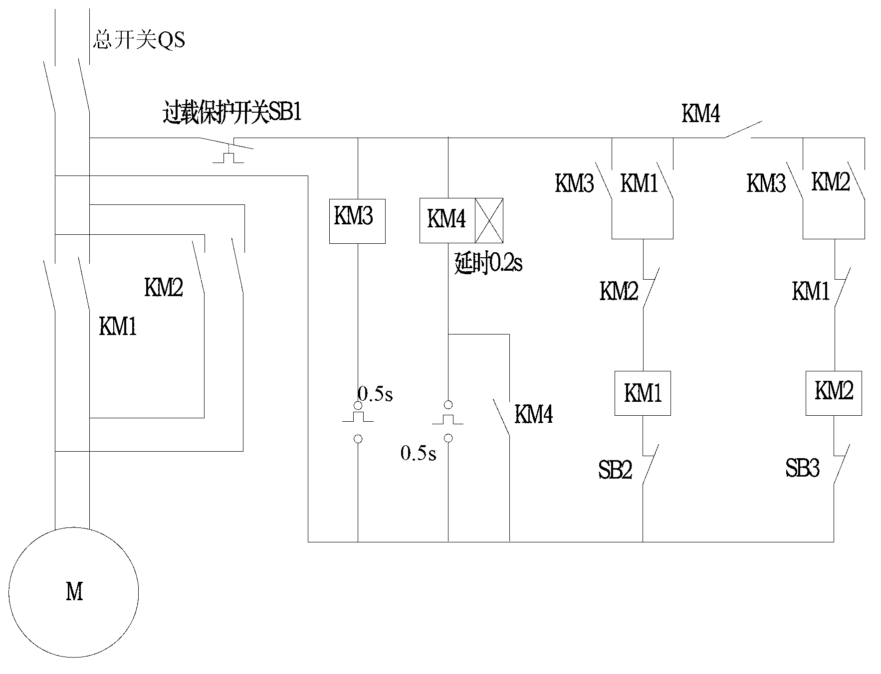
[0030] This embodiment is a monocular vision and binocular vision conversion device for a small robot, which consists of a wireless communication camera 1, a transmission component, a power component and a control component.

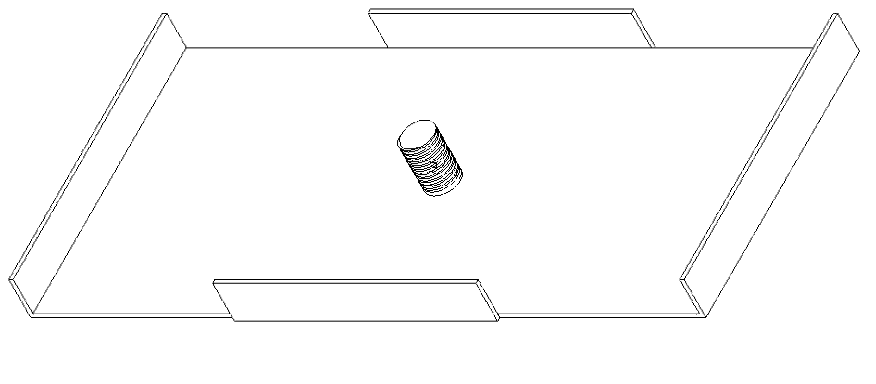
[0031] Refer to appendix 1 and appendix figure 2 , the wireless communication camera is connected with the screw in the middle of the camera fixing plate 14 through the threaded hole at the bottom, and the movement of the wireless communication camera is restricted by the cards around the camera fixing plate, thereby the wireless communication camera is fixed on the camera fixing plate.

[0032] The transmission assembly is composed of a rotary motion-to-linear motion assembly and guide rails. In this embodiment, the rotary motion part of the transmission assembly is a screw 11, and the linear motion part is a slider 9. There is a threaded through hole in the middle o...


PUM


Abstract

The invention provides a monocular vision and binocular vision switching device for a small robot, comprising a wireless communication camera, a transmission assembly, a power assembly and a control assembly, wherein the transmission assembly is composed of a rotary motion and linear motion switching assembly and a guide rail, a camera fixing plate is fixed on a linear motion component of the transmission assembly, baffles are arranged at two sides of the transmission assembly, each baffle is provided with a trigger switch for the control assembly, the two ends of a rotary motion component of the transmission assembly are connected with the baffles by virtue of bearings, and one end of the rotary motion component penetrates through the baffles to be connected with the power assembly by virtue of a coupler; and the control assembly comprises a control circuit board as well as a first channel trigger switch and a second channel trigger switch which are respectively arranged on the baffles at the two sides of the transmission assembly. The monocular vision and binocular vision switching device provided by the invention realizes mutual switching between monocular vision and binocular vision, so that the small robot can be more widely applied; and binocular base line distance is adjustable, so that better rebuilding effect can be obtained by regulating base line distance.

Description

technical field [0001] The invention relates to the technical field of robot vision, in particular to a monocular vision and binocular vision conversion device for a small robot. Background technique [0002] The purpose of machine vision research is to enable the machine to have the ability to recognize three-dimensional environment information through two-dimensional image information. This ability not only enables the machine to perceive the geometric information (such as shape, position, posture movement, etc.) They can be further described, stored, identified and understood. At present, machine vision is mainly used for 3D reconstruction and distance calculation. In vision research, it is mostly divided into monocular stereo vision, binocular and multi-eye stereo vision, and currently binocular or monocular cameras are mostly used. [0003] The monocular vision method is a method of 3D reconstruction using one camera. The following two methods are often used: 1. Deri...

Claims


Application Information

Patent Timeline
Patent Type & Authority Applications(China)
IPC IPC(8): G05D1/02
Inventor 于薇薇乔静王森陈亚胜罗巍冯华山王润孝谭小群李树军白晶赵妮翟明敏
Owner NORTHWESTERN POLYTECHNICAL UNIV
Learn More