Control device for continuously variable transmission

A continuously variable transmission and control device technology, applied in transmission parts, transmission control, clutch, etc., can solve the problems of increasing or decreasing the clamping pressure, and achieve the effect of improving toughness

Active Publication Date: 2014-11-05
HONDA MOTOR CO LTD
View PDF5 Cites 0 Cited by
  • Summary
  • Abstract
  • Description
  • Claims
  • Application Information

AI Technical Summary

Problems solved by technology

In the technology described in Patent Document 1, a lock-up clutch is used as a clutch, and its engagement pressure is increased or decreased over time.

Method used


Image

  • Control device for continuously variable transmission
  • Control device for continuously variable transmission
  • Control device for continuously variable transmission

Examples


Embodiment

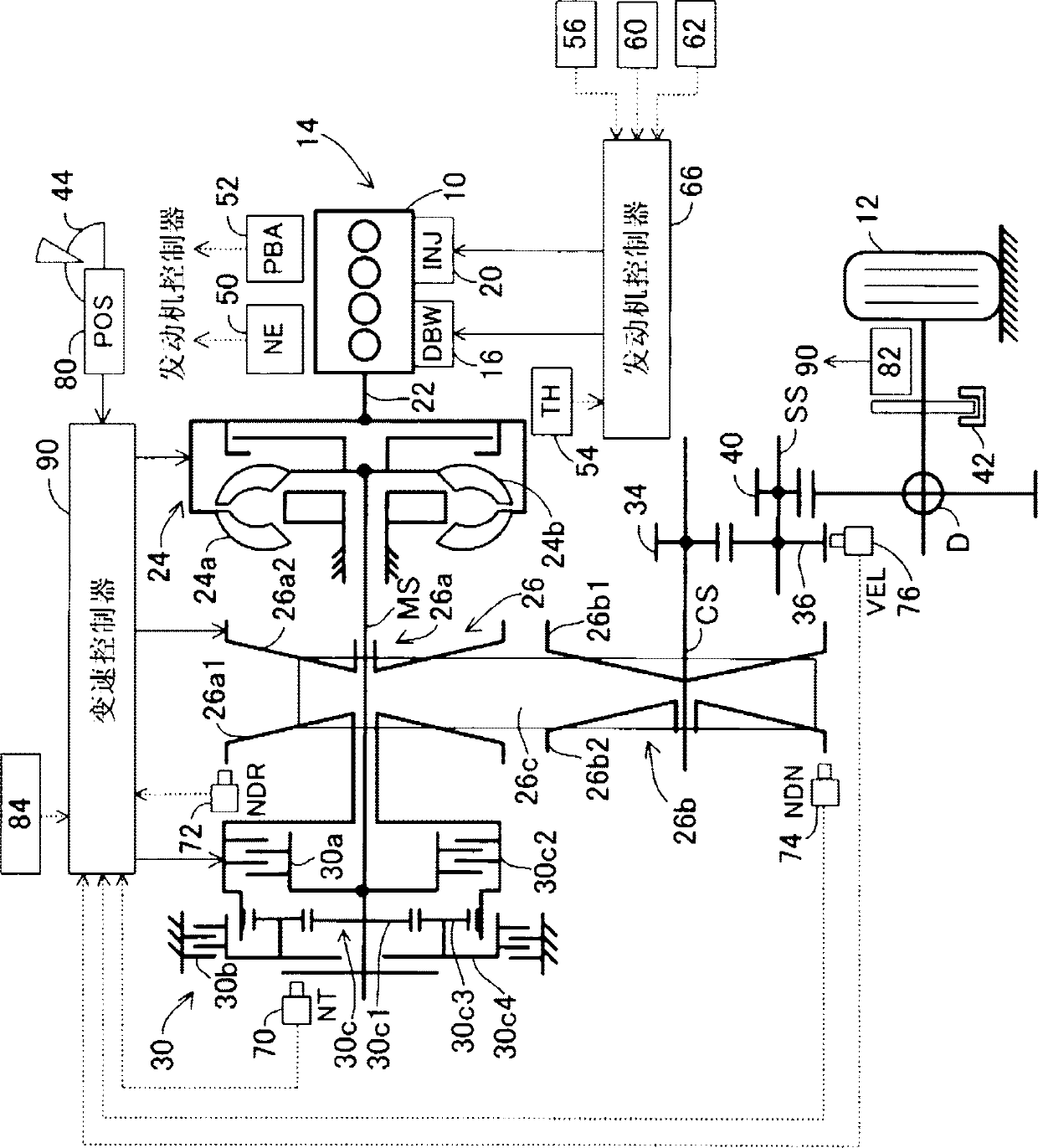
[0035] figure 1 It is a schematic diagram generally showing a control device of a continuously variable transmission (automatic transmission) according to an embodiment of the present invention.

[0036] figure 1 In , reference numeral 10 denotes an internal combustion engine (drive source. Hereinafter referred to as "engine"). Engine 10 is mounted in a vehicle (shown partially by drive wheels 12 etc.) 14 .

[0037] The mechanical connection between the throttle valve (not shown) arranged in the air intake system of the engine 10 and the accelerator pedal (not shown) arranged at the driver's seat of the vehicle is disconnected, and the throttle valve is connected with an actuator composed of an electric motor or the like. The DBW (Drive By Wire) mechanism 16 is driven.

[0038] The intake air whose amount is adjusted by the throttle valve flows through the intake manifold (not shown), and is mixed with fuel injected from the injector (fuel injection valve) 20 near the intak...


PUM


Abstract

In an apparatus for controlling a belt type CVT 26 connected to an engine (prime mover) 10 mounted on a vehicle 14 through a forward clutch 30a to change power of the engine in speed and transmit the power to a driven wheel 12 of the vehicle 14, it is configured to determine whether it is in a predetermined operating condition where an operator is likely to apply a panic brake or the like (S10, S12), set a first value as a friction coefficient µ of the clutch to calculate and control a desired supply hydraulic pressure based on the first value when the determination result is negative (S14, S16), and set a second value greater than the first value to calculate and control the desired supply hydraulic pressure based on the second value when the determination result is affirmative (S18 to S22). With this, even when excessive input torque is transmitted from the driven wheel upon panic braking or the like under the predetermined operating condition, since the desired supply hydraulic pressure is calculated to decrease with increasing friction coefficient, it becomes possible to calculate the desired supply hydraulic pressure to be a lower value compared to a case where it is not in the predetermined operating condition by setting the second value of greater than the first value.

Description

technical field [0001] The present invention relates to a control device of a continuously variable transmission (automatic transmission). Background technique [0002] Recently, there is known a torque fuse control in which the engagement pressure of a clutch arranged in series with a belt-type continuously variable transmission (automatic transmission) is controlled to slip ahead of the continuously variable transmission, thereby preventing excessive transmission to the belt. Great torque. As an example, the technique described in patent document 1 is mentioned. In the technique described in Patent Document 1, a lock-up clutch is used as a clutch, and its engagement pressure is increased or decreased over time. [0003] prior art literature [0004] patent documents [0005] Patent Document 1: Japanese Patent Laid-Open No. 2004-251360 Contents of the invention [0006] The problem to be solved by the invention [0007] In the case of connecting a belt-type continuo...

Claims


Application Information

Patent Timeline
Patent Type & Authority Patents(China)
IPC IPC(8): F16D48/02F16H59/54F16H61/12F16H61/662
CPCF16H2061/6618F16D2500/30402F16D2500/50236F16H2057/014F16H61/66272F16D2500/1026F16D48/066F16D2500/70406F16H2061/0087
Inventor 户塚博彦
Owner HONDA MOTOR CO LTD
Why Eureka
Try Eureka