Device for electric circuit monitoring

A technology of electric circuit and current detection device, which is applied in the direction of circuit device, emergency protection circuit device, emergency protection device with automatic disconnection, etc., which can solve the problems of long shut-off pulse, harmful function, and consumption

Inactive Publication Date: 2013-02-20
FESTO AG & CO KG
View PDF5 Cites 0 Cited by
  • Summary
  • Abstract
  • Description
  • Claims
  • Application Information

AI Technical Summary

Problems solved by technology

However, this has the disadvantage that the switch-off pulse can become so long that the response to the switch-off can be important for the load and thus possibly also be detrimental to the function.
But this means an increase in cost

Method used


Image

  • Device for electric circuit monitoring

Examples


Embodiment Construction

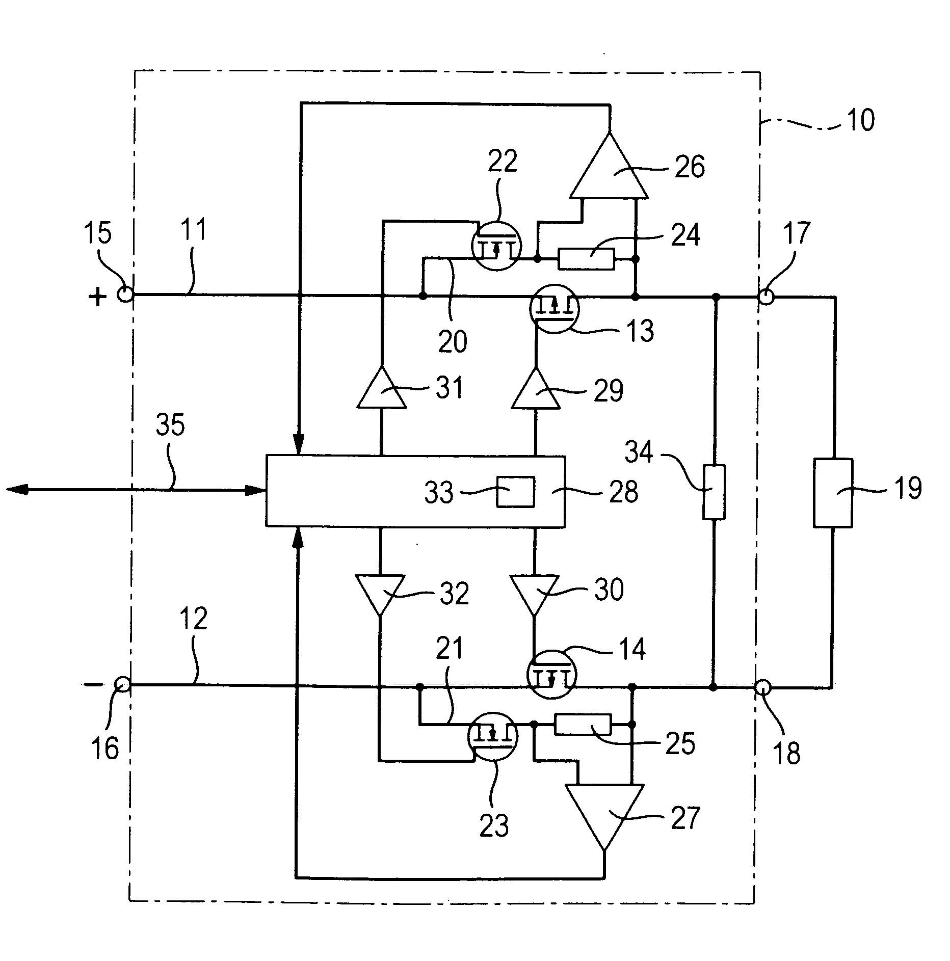
[0016] In the exemplary embodiment shown in the single figure, an electrical device 10 for loop monitoring comprises two current paths 11 , 12 , in which switching sections of transistors 13 , 14 are connected in each case. The two current paths 11 , 12 are connected on the one hand to two supply voltage terminals 15 , 16 of a supply voltage source not shown here and on the other hand to an external consumer 19 via two consumer terminals 17 , 18 , In principle, there can also be a plurality of consumers, which can also be non-ohmic consumers (for example capacitive and / or inductive and / or ohmic consumers).

[0017] Parallel branches 20 , 21 each consisting of a series circuit of a further transistor 22 , 23 and a low-current shunt 24 , 25 are connected in parallel with the switching sections of the two transistors 13 , 14 . The voltages tapped at the low current shunts 24 , 25 are fed to current shunt sensors 26 , 27 respectively, which generate a current-dependent signal at t...


PUM


Abstract

The invention relates to a device for electric circuit monitoring an electrical load circuit comprising at least one electrical load (19), wherein two supply voltage connections (15, 16) are connected to the two load connections (17, 18) by means of current paths (11, 12) each comprising one first semiconductor switch (13, 14). The current detecting means (26, 27) serve to detect the current in each of the two current paths (11, 12). The series connection of a further second semiconductor switch (22, 23) and a low-current shunt (24, 25) is connected in parallel with each high-current shunt in each of the two current paths (11, 12), wherein the two connections of the low-current shunt (24, 25) are each connected to the current detecting means (26, 27).

Description

technical field [0001] The invention relates to a device for electrical circuit monitoring of a consumer circuit comprising at least one electrical consumer, wherein two supply voltage terminals are each connected to two consumer terminals via a current path with a first semiconductor switch. Background technique [0002] Such a device is used, for example, as a safety disconnection system in order to deactivate in particular energy-rich device components when a fault situation or a malfunction is detected. In such cases, in particular the current or the supply voltage is switched off and / or a fault message and / or a fault display is generated. The consumers can be separated single-channel or two-channel. Such a safety disconnection system is known, for example, from WO 02 / 095282 A1. In order to ensure that the semiconductor switching element is actually able to open the safety circuit even in a dangerous situation, it is repeatedly disconnected briefly in a known manner an...

Claims


Application Information

Patent Timeline
Patent Type & Authority Applications(China)
IPC IPC(8): H03K17/18H02H3/24H02H3/32
CPCH03K17/18H03K2217/0027
Inventor M.格尔科W.罗贝
Owner FESTO AG & CO KG
Why Eureka
Try Eureka