
Rotation arm type wire laying-off apparatus
A pay-off device and a rotary arm-type technology, which is applied in the field of a rotary-arm pay-off device, can solve problems such as damage to the phosphating film of the disk element, increase in the working environment, and influence on the quality of wire drawing, so as to avoid surface damage, facilitate operation, and guarantee The effect of product quality
- Summary
- Abstract
- Description
- Claims
- Application Information
AI Technical Summary
Problems solved by technology
Method used
Image

Examples
Embodiment Construction
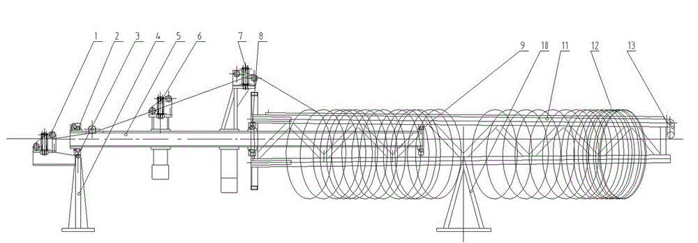
[0011] Such as figure 1 As shown, the pay-off device includes No. 1 wire roller 1, No. 1 bearing 2, swing bearing seat 3, front bracket 4, rotating shaft 5, No. 2 wire roller 6, No. 3 wire roller 7, No. 2 bearing 8, No. 3 Bearing 9, tail support 10 and wire bearing arm 11, No. 1 bearing 2 is installed in the front portion of rotating shaft 5, No. 2 bearing 8 is installed in the middle part of rotating shaft 5, No. 3 bearing 9 is installed in the afterbody of rotating shaft 5, the front portion of rotating shaft 5 passes through a The No. 2 bearing and the swing bearing seat 3 are installed on the front bracket 4, and the rotating shaft 5 penetrates into the thread-supporting arm 11 and is installed in the thread-carrying arm 11 through No. 2 bearing 8 and No. 3 bearing 9, and the thread-carrying arm 11 is supported and installed on the tail bracket On 10, No. 1 wire roller 1 is installed on the front support 4, and No. 2 wire roller 6, No. 3 wire roller 7 are installed on the ...
PUM
 Abstract
Description
Claims
Application Information