Slugging cleaning device of silicon steel furnace and application thereof

A technology for cleaning equipment and silicon steel, applied in descaling equipment, furnaces, furnace components, etc., can solve the problems of great influence on continuous production, and achieve the effect of satisfying continuous production

Inactive Publication Date: 2013-02-27
UNIV OF SCI & TECH LIAONING
View PDF7 Cites 12 Cited by
  • Summary
  • Abstract
  • Description
  • Claims
  • Application Information

AI Technical Summary

Problems solved by technology

This kind of furnace repair generally requires the heating furnace to stop

Method used


Image

  • Slugging cleaning device of silicon steel furnace and application thereof

Examples


Embodiment Construction

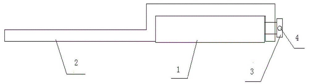
[0013] Such as figure 1 As shown, a silicon steel furnace slag cleaning device is composed of a steel plate 1, a slag removal rod 2, a locking bolt 3 and a crowbar 4. The steel plate 1 is a large steel plate with a thickness of 230 mm, a width of 1150 mm, and a length of 9000 mm. One end of the slag removal rod 2 is straight, the other end is hook-shaped, and there are locking holes and locking bolts 3 at the tail. The slag removal rod 2 is installed on the On the steel plate 1, the effect of the slag removal rod 2 is to clean it up by bumping the slag on the water beam in the heating furnace. On the cap of locking bolt 3, have circular hole, insert prying roller 4 in circular hole, crowbar 4 is that a diameter is 30 millimeters steel pipes or steel bar.

[0014] An application of a silicon steel furnace slag cleaning device, the application method is as follows:

[0015] Put the silicon steel slag cleaning device on the roller table on the tapping side of the heating furnac...


PUM


Abstract

The invention discloses a slugging cleaning device of a silicon steel furnace and application thereof. The device is directly used for removing slugging on a beam and guarantees that a heating furnace normally produces. The silicon steel slugging cleaning device comprises a steel plate, a slag removing rod, a locking bolt and a prying rod, and the application of the cleaning device comprises placing the cleaning device of the silicon steel furnace on a roller way on a steel discharge side of the heating furnace, adjusting positions of the slag removing rod of the silicon steel slugging cleaning device, enabling the slag removing rod to align at accumulated slag on a water beam in the heating furnace, ascending the height of a steel drawing rod in the heating furnace to be equal to that of the silicon steel slugging cleaning device, advancing the steel drawing rod, pushing the silicon steel slugging cleaning device to go forward together, and breaking and shedding the accumulated slag on the beam under the effect of the slag removing rod when the slag removing rod is contacted with the accumulated slag on the water beam. The device can serve as matched equipment for producing oriented silicon steel, and greatly meets requirements for steel continuous production of the oriented silicon steel.

Description

technical field [0001] The invention relates to a cleaning device for a steel rolling heating furnace and its application, in particular to a silicon steel furnace slag cleaning device and its application. Background technique [0002] The production process of grain-oriented silicon steel is complicated, and the production process parameters of each process require high control precision. Its production process represents the highest level of steel production process in the world. Among them, the hot rolling production process of oriented silicon steel requires high-temperature heating and a long time in the furnace. During this high-temperature and long-term continuous heating process, a large amount of iron oxide scale is produced on the surface of the slab, and the iron oxide scale is melted under the action of high temperature. The surface of the slab flows to the walking water beam in the heating furnace, and after solidification, it accumulates and becomes thicker, ca...

Claims


Application Information

Patent Timeline
IPC IPC(8): F27D25/00
Inventor 冯亮花刘坤
Owner UNIV OF SCI & TECH LIAONING
Why Eureka
Try Eureka