Continuous die

A mold and connection technology, applied in the field of continuous molds, can solve problems affecting production efficiency, loss, poor guiding processing quality, etc.

Active Publication Date: 2018-07-20
HISENSE (SHANDONG) AIR CONDITIONING CO LTD
View PDF6 Cites 3 Cited by
  • Summary
  • Abstract
  • Description
  • Claims
  • Application Information

AI Technical Summary

Problems solved by technology

In the continuous mold production process, when the material belt is conveyed manually or automatically, since the large continuous mold is generally more than 3m, there is a small error in the initial position feeding, which will be enlarged during the subsequent fabric processing, resulting in th

Method used


Image

  • Continuous die
  • Continuous die
  • Continuous die

Examples


Embodiment Construction

[0023] The specific embodiments of the present invention will be described in detail below in conjunction with the accompanying drawings, but the present invention can be implemented in many different ways defined and covered by the claims.

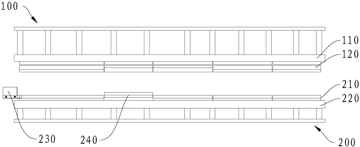
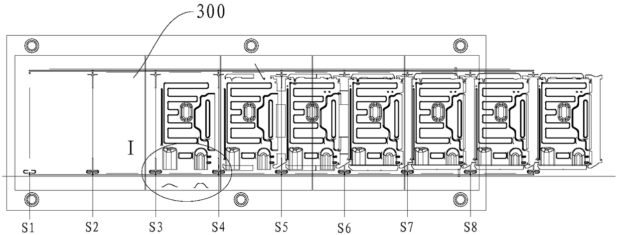
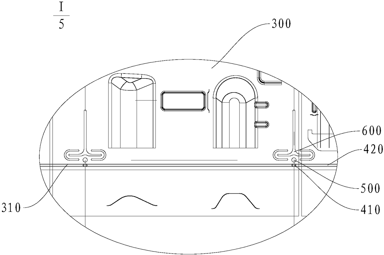
[0024] refer to figure 1 , the continuous mold in one embodiment of the present invention includes an upper mold 100, a lower mold 200 and a strip guiding structure. The strip 300 is set on the lower mold 200 . The upper mold 100 includes a fixing plate 110 and an upper stripper plate 120 , and the lower mold 200 includes a lower template 210 and a lower backing plate 220 . Such as figure 2 and image 3 As shown, the edge width of both sides of the material strip 300 and the portion used for material connection are provided with reinforcing ribs 310 . The strip guide structure includes a guide groove 420 and a guide pin 410 , the guide groove 420 is arranged on the rib 310 , and the guide pin 410 is fixedly arranged on each station o...


PUM


Abstract

The invention discloses a continuous die, relates to the technical field of dies, and aims at providing a continuous die capable of preventing unable alignment due to material strip softening, correctin feeding alignment, smooth in feeding and simple in structure. The continuous die comprises an upper die, a lower die and a material strip alignment structure, a material strip is arranged on the lower die, and strengthening ribs are arranged on the two sides of the material strip. The material strip alignment structure comprises alignment grooves and alignment pins, and the alignment grooves are formed in the strengthening ribs. The alignment pins are fixedly arranged on all stations of the lower die and are matched with the alignment grooves, and the movement of the material strip is guided.

Description

technical field [0001] The invention relates to the technical field of molds, in particular to a continuous mold. Background technique [0002] At present, structural parts such as air-conditioning partitions, motor brackets, and right side panels are produced using continuous molds to improve production efficiency and reduce processing costs. The continuous mold is different from the process mold. The common process mold requires several punching machines to process according to the steps. Each punching machine needs to be manually responsible and needs to transfer the semi-finished products completed in the previous process. After using the continuous die solution, all processes can be completed on a single large-tonnage equipment, and the continuous production of sheet metal parts can be realized by using an automatic punching machine, and the production efficiency is increased by dozens of times. In the process of continuous mold production, when the material belt is co...

Claims


Application Information

Patent Timeline
IPC IPC(8): B21D37/10B21D43/02B21D43/00
CPCB21D37/10B21D43/003B21D43/021
Inventor 赵现枫李玉乾
Owner HISENSE (SHANDONG) AIR CONDITIONING CO LTD
Why Eureka
Try Eureka