Automatic gunpowder filling mechanism for firecrackers

An automatic and powder-charging technology, applied in pyrotechnics, offensive equipment, weapon types, etc., can solve problems such as safety accidents, low production efficiency, and poor consistency of production quality, and achieve the goals of improving production efficiency, simple structure, and improving production safety Effect

Active Publication Date: 2013-02-27
中国兵器装备集团自动化研究所有限公司
View PDF5 Cites 1 Cited by
  • Summary
  • Abstract
  • Description
  • Claims
  • Application Information

AI Technical Summary

Problems solved by technology

[0004] In order to overcome the disadvantages of safety accidents, low production efficiency, and poor production quality consistency in the production of fireworks and firecrackers in the prior art, the present invention provides an automatic charging mechanism for firecrackers, which can realize automatic metering and filling of firecrackers

Method used


Image

  • Automatic gunpowder filling mechanism for firecrackers
  • Automatic gunpowder filling mechanism for firecrackers
  • Automatic gunpowder filling mechanism for firecrackers

Examples


Embodiment 1

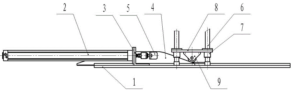
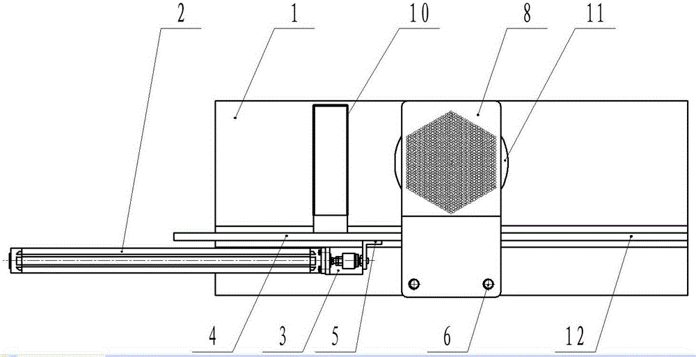
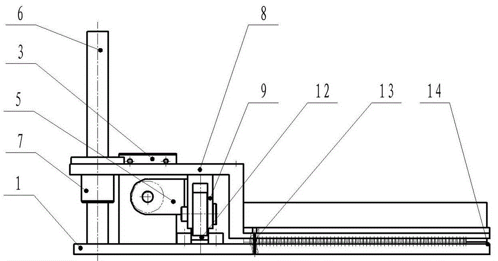
[0018] figure 1 Is the front view of the overall structure of the present invention, figure 2 Is a top view of the overall structure of the present invention, image 3 It is a side view of the overall structure of the present invention. in figure 1 ― image 3 Among them, the automatic firecracker charging mechanism of the present invention includes a table top 1, a power cylinder 2, a power cylinder mounting plate 3, an inclined plane block 4, a mounting block 5, a column 6, a sliding bearing 7, a lifting plate 8, a sliding piece 9, and a medicine box 10. Measuring plate 11, positioning groove 12, medicine punching head 13, scraping plate 14. The connection relationship is that the power cylinder mounting plate 3, the positioning groove 12, and the column 6 are fixedly installed on the table top 1. The power cylinder 2 is fixedly installed on the power cylinder mounting plate 3, the inclined plane block 4 is placed in the positioning groove 12, and the front end of the power...

Embodiment 2

[0021] The basic structure of this embodiment is the same as that of embodiment 1, except that the number of the medicine heads is 1,141.

[0022] The medicine box 10, the medicine scraping block 14, and the metering plate 11 in the present invention complete the constant volume metering of medicine under the action of the power cylinder 2 and the inclined plane block 4. Under the action of the power cylinder 2 and the inclined block 4, the punching head 13 works together with the column 6, the sliding bearing 7, the sliding member 9, and the lifting plate 8 to complete the discharge of the medicine from the hole of the metering plate 11.

[0023] The working process of the firecracker automatic charging mechanism of the present invention is that the firecracker medicine is delivered into the medicine box 10 by the medicine mixing mechanism before the work starts. After the work starts, the power cylinder 2 drives the inclined plane block 4 through the mounting block 5. Since the m...


PUM


Abstract

The invention provides an automatic gunpowder filling mechanism for firecrackers. A power cylinder installing plate, a positioning groove and a column in the automatic gunpowder filling mechanism are fixedly installed on a table face plate. A power cylinder is fixedly installed on the power cylinder installing plate, an inclined plane block is placed in the positioning groove, and the front end of the power cylinder is connected with the inclined plane block through an installing block. A lifting plate is slidably installed on the column through a sliding bearing, the upper end of a sliding part is fixed on the bottom surface of the lifting plate, and the lower end of the sliding part is contacted with the inclined plane block. A gunpowder box is fixedly installed on the side of the inclined plane block, and a gunpowder scraping block is installed on the lower end face of the gunpowder box. A measurement plate is arranged below the lifting plate and installed on the table face plate in an embedded mode. The gunpowder scraping block is contacted with the measurement plate. The automatic gunpowder filling mechanism for the firecrackers is simple in structure and convenient to use, firecracker gunpowder can be automatically measured and filled, production safety and production efficiency are improved.

Description

Technical field [0001] The invention belongs to the technical field of civilian high-risk production, and specifically relates to a firecracker automatic charging mechanism. Background technique [0002] Fireworks and firecrackers is a traditional Chinese craft industry with a history of nearly 1,400 years. Only in recent years has it started to transition from home workshop-style operations to semi-mechanical production methods. Basically, each process is manual or manual single-machine production. Fireworks and firecrackers are flammable and explosive. They belong to high-risk civil industries and are prone to safety accidents. The current production situation has problems such as human-machine mixed flow operation that cannot effectively guarantee personnel safety, low production efficiency, poor production quality consistency, and great harm to operators. Manufacturers have an urgent need for safe, efficient and precise industry-specific equipment. [0003] At present, the cha...

Claims


Application Information

Patent Timeline
Patent Type & Authority Applications(China)
IPC IPC(8): F42B4/30
Inventor 吴斌方浩舟周丽娟汪炼诸洪石义官张博王雪晶
Owner 中国兵器装备集团自动化研究所有限公司
Why Eureka
Try Eureka