Ground cross-hole resistivity ct measurement cable crossing device

A technology of resistivity and road crossing, which is applied in the field of ground resistivity CT advance prediction, can solve the problems of affecting measurement work, long construction period, and easy damage, and achieves easy disassembly and maintenance, strong anti-rolling ability, and variable length Effect

Active Publication Date: 2016-06-01
SHANDONG UNIV
View PDF3 Cites 0 Cited by
  • Summary
  • Abstract
  • Description
  • Claims
  • Application Information

AI Technical Summary

Problems solved by technology

[0005] The traditional cross-hole resistivity CT method on the ground is not particularly good for the detection of boreholes on both sides of the road. It is directly run over by passing vehicles, which is easy to be damaged and affects the measurement work; second, the high placement method: that is to find two tall (usually greater than 8 meters) shelves on both sides of the road in advance, and then place the cables on a high place to cross On the road, due to the heavy weight of the cable, the poles on both sides are too high, and are restricted by the wind, it is difficult to fix, move, and operate; It is a special machine and has a great impact on road traffic; fourth, the traffic police department is dispatched for traffic control. This method seriously affects urban traffic, and it is difficult to be allowed to be used on urban main roads
All of the above methods have major shortcomings, which seriously affect the implementation and application efficiency of the ground trans-hole resistivity CT method.

Method used


Image

  • Ground cross-hole resistivity ct measurement cable crossing device
  • Ground cross-hole resistivity ct measurement cable crossing device
  • Ground cross-hole resistivity ct measurement cable crossing device

Examples


Embodiment

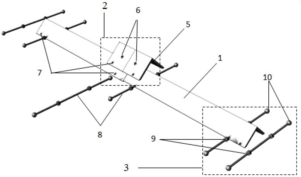
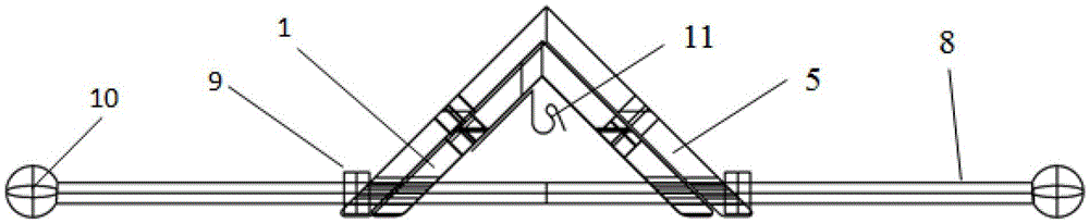
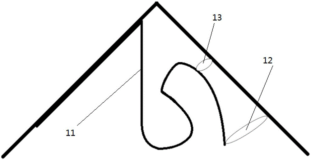
[0025] Examples: Figure 1~4 The device as a whole is in the shape of a triangular steel strip with long legs, which includes a split member 1, a connecting member 2, and a holder 3. The device is divided into inner and outer sides. The inner side is equipped with a fixed hook 11, the hook entrance 12 is large, and the seal 13 is small. .

[0026] The device is integrally connected by split members 1 of different lengths through connecting members 2, and the strip angle steel is connected by connecting angle steel 5 through connecting hole 6 and connected by corresponding bolts.

[0027] The length of the split member 1 of the device is divided into different specifications, and different combinations can be selected according to the width of the road 12, suitable for use in different areas, and easy to transport after being split. When using, select the corresponding combination and combine it into a whole device.

[0028] The cable 4 is fixed inside the device, and fixed hooks 11...


PUM


Abstract

The invention specifically discloses a road crossing device of a ground cross-hole resistivity CT (Computed Tomograpphy) measurement cable. The device comprises a plurality of split elements, a plurality of jointing elements and a plurality of fixing devices, wherein the split elements are connected by virtue of the jointing elements; the fixing devices are used for fixing the split elements and the jointing elements; the cross sections of the split elements are triangular strip-type steel structures; and the inner sides of the split elements are provided with cable fixing devices. The device has the following beneficial effects: the device can be used for simultaneously measuring drilled holes on two sides after being arranged on a road surface; after measurement, the cable is taken out, the fixing devices are detached, the whole device is detached into split devices, is small in size after detachment, and convenient to carry; each connection part of the device is a movable connection which is convenient and reliable and can be easily detached and maintained; and the whole measurement device (comprising the connecting elements) is made of a rigid metal material, is strong in anti-compaction capability, and can be moved on the road conveniently.

Description

Technical field [0001] The invention relates to a ground resistivity CT advanced prediction technology, in particular to a ground cross-hole resistivity CT measuring cable crossing device. Background technique [0002] In recent years, with the acceleration of urbanization, the construction of subways has achieved unprecedented development. During the construction of urban subways, bad geological conditions such as karst trenches, karst caves, karst caves, underground rivers, and broken zones have a huge impact on the construction of subway underground excavation. If these bad geological bodies cannot be detected or predicted in advance, unforeseen geological disasters are likely to occur, such as water inrush, mud outburst, and collapse. The consequences of these geological disasters are ranging from damaging or destroying machinery, submerging tunnels, and interrupting normal construction; on the other hand, causing heavy casualties, resulting in huge economic losses, and even...

Claims


Application Information

Patent Timeline
Patent Type & Authority Patents(China)
IPC IPC(8): G01V3/00
Inventor 张文俊李术才苏茂鑫邱道宏张永伟
Owner SHANDONG UNIV
Why Eureka
Try Eureka