
Battery charging circuit and control circuit and control method thereof

A control circuit and battery charging technology, which is applied in the direction of battery circuit devices, circuit devices, control/regulation systems, etc., can solve problems such as requirements, unsatisfactory frequency range, and large frequency range of battery charging circuits, etc., and achieve simple circuit structure Effect

Active Publication Date: 2013-02-27
CHENGDU MONOLITHIC POWER SYST
View PDF6 Cites 18 Cited by
  • Summary
  • Abstract
  • Description
  • Claims
  • Application Information

AI Technical Summary

Problems solved by technology

However, the frequency range of the traditional battery charging circuit controlled by the hysteresis method is relatively large, which cannot meet the requirements for the application of the frequency range.

Method used


Image

  • Battery charging circuit and control circuit and control method thereof
  • Battery charging circuit and control circuit and control method thereof
  • Battery charging circuit and control circuit and control method thereof

Examples


Embodiment Construction

[0032] Specific embodiments of the present invention will be described in detail below, and it should be noted that the embodiments described here are only for illustration, not for limiting the present invention. In the following description, numerous specific details are set forth in order to provide a thorough understanding of the present invention. It will be apparent, however, to one of ordinary skill in the art that these specific details need not be employed to practice the present invention. In other instances, well-known circuits, materials or methods have not been described in detail in order to avoid obscuring the present invention.

[0033] Throughout this specification, reference to "one embodiment," "an embodiment," "an example," or "example" means that a particular feature, structure, or characteristic described in connection with the embodiment or example is included in the present invention. In at least one embodiment. Thus, appearances of the phrases "in on...


PUM


Abstract

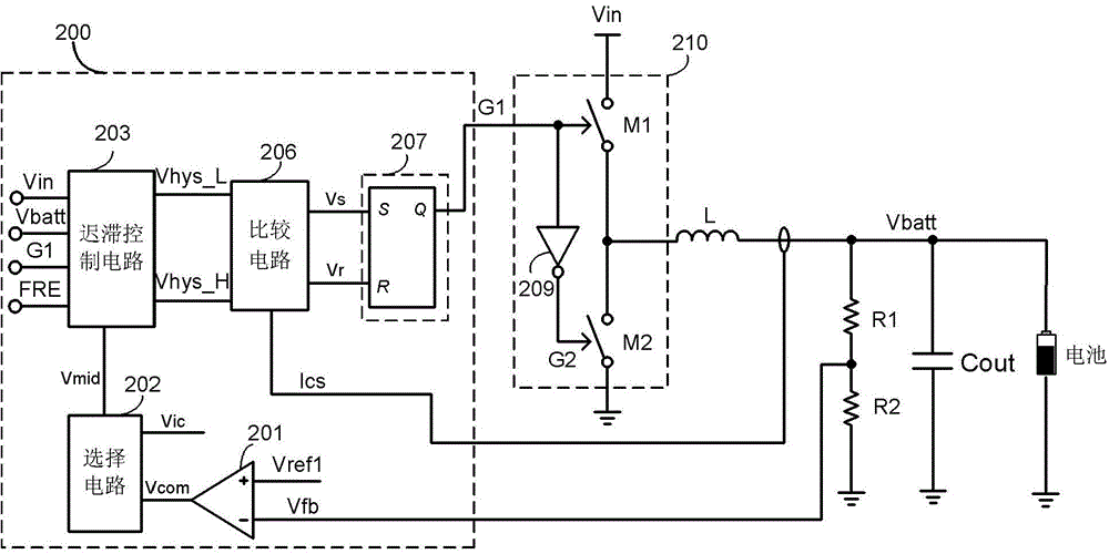
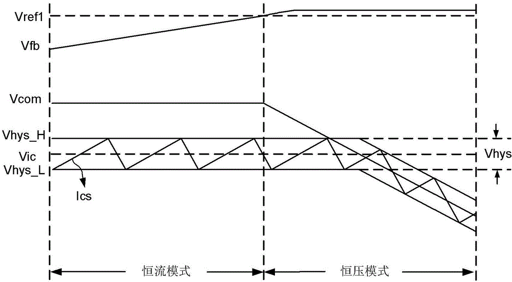
The invention provides a battery charging circuit and a control circuit and control method of the battery charging circuit. The battery charging circuit is used for controlling the charging of a battery. The control circuit comprises a feedback amplifier, a selection circuit, a delay control circuit, a comparison circuit and a logic circuit, wherein the feedback amplifier receives a feedback signal and a feedback reference signal and outputs a feedback amplification signal from an output end; the selection circuit selects a smaller one of a current reference signal and the feedback amplification signal as a current control signal and outputs the current control signal to the output end; the delay control circuit inputs a voltage, a charging voltage and a control signal on the basis of the current control signal and outputs a current lower limit signal from a first output end and a current upper-limit signal from a second output end; the comparison circuit outputs a setting signal from the first output end and a resetting signal from the second output end on the basis of the current upper-limit signal, the current lower-limit signal and a current detection signal; and the logic circuit outputs a control signal from the output end on the basis of the setting signal and the resetting signal.

Description

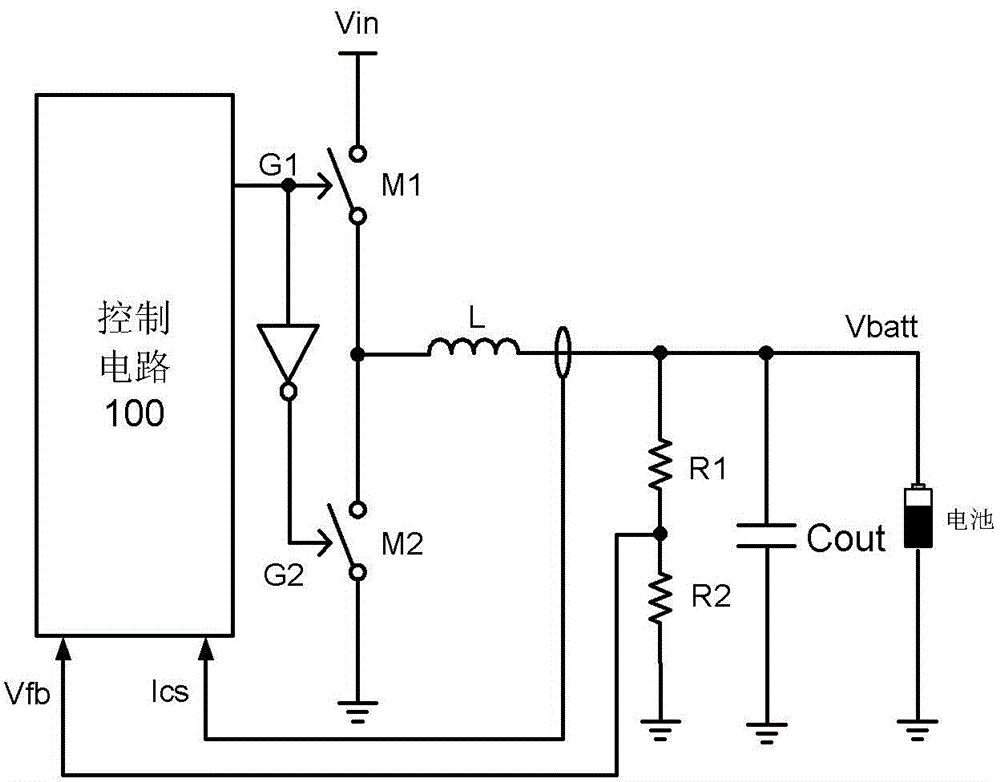
technical field [0001] The present invention relates to a switch circuit, and more specifically, the present invention relates to a battery charging circuit in the switch circuit, a control circuit and a control method thereof. Background technique [0002] The battery charging circuit is used to control the charging of the battery. Normally, the working process of the battery charging circuit is divided into two stages, the first is the constant current stage, and then the constant voltage stage. The traditional battery charging circuit using hysteresis control realizes constant current control during battery charging by limiting the upper and lower limits of the inductor current. Such as figure 1 As shown, the control circuit 100 detects the inductor current, generates the current detection signal Ics, and detects the battery voltage Vbatt through the feedback resistors R1 and R2 to generate the feedback voltage Vfb. Based on the current detection signal Ics and the fee...

Claims


Application Information

Patent Timeline
IPC IPC(8): H02J7/00H02M3/158H02M1/00
CPCH02J7/00H02M3/158H02J2207/20H02M1/0025
Inventor 白真贵徐敏李小青
Owner CHENGDU MONOLITHIC POWER SYST
Features
  • Generate Ideas
  • Intellectual Property
  • Life Sciences
  • Materials
  • Tech Scout
  • Unparalleled Data Quality
  • Higher Quality Content
  • 60% Fewer Hallucinations
Learn More