Buck-boost control circuit of LED (Light Emitting Diode) lamp
A technology for LED lamps and control circuits, which is applied in the layout of electric lamp circuits, control/regulation systems, electric light sources, etc. In line with the LED working characteristics and other issues, the overall circuit structure is simple, the constant current characteristics are good, and the reliability is high.
- Summary
- Abstract
- Description
- Claims
- Application Information
AI Technical Summary
Problems solved by technology
Method used
Image
Examples
Embodiment
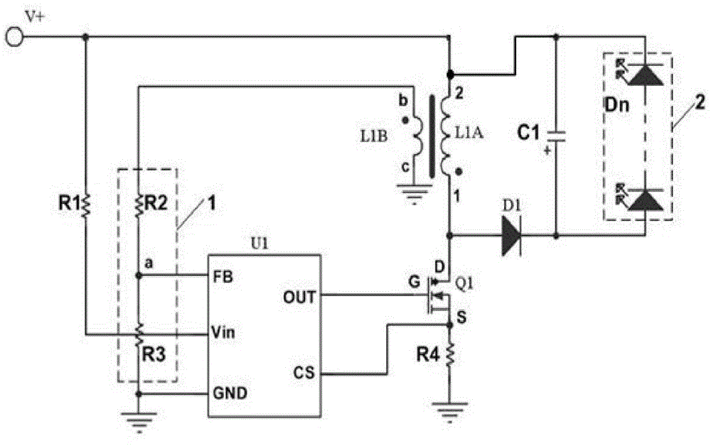
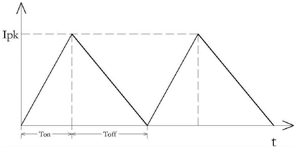
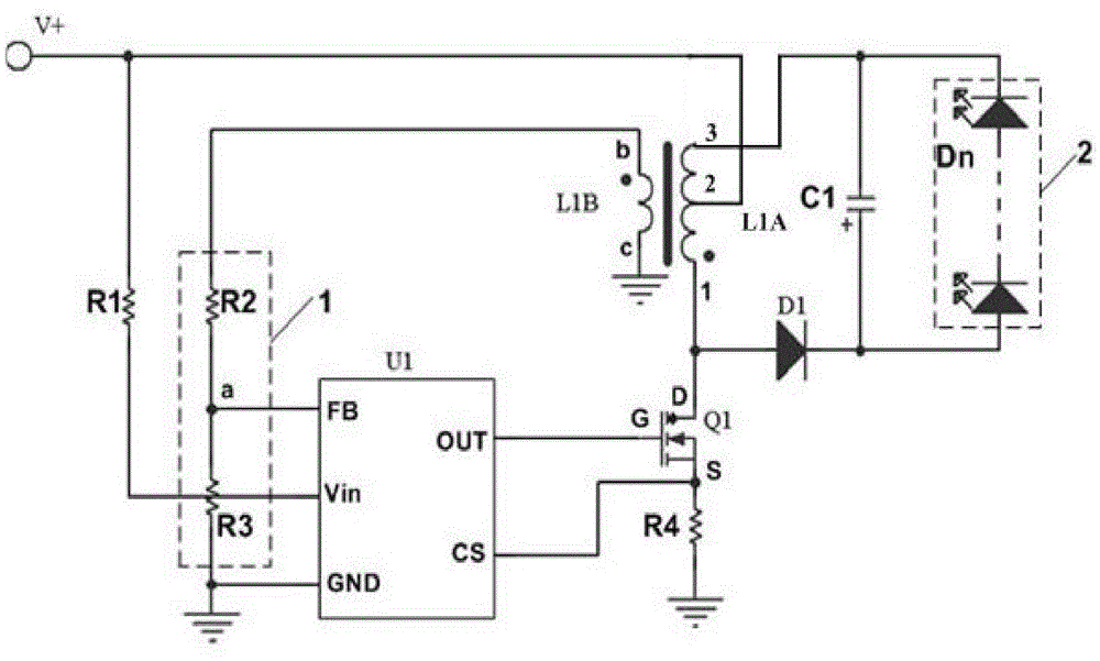
[0020] Example: such as figure 1 As shown, the present invention is a buck-boost control circuit for LED lamps, the switch tube Q1 is a MOSFET, and the pulse width modulation circuit U1 is a pulse width modulation chip that does not need a secondary side control circuit and a loop compensation circuit; the gate of the switch tube Q1 The pole G is connected to the output (OUT) terminal of the pulse width modulation circuit U1, the source S is connected to the power ground through the current sampling resistor R4, the drain D is connected to the DC power supply V+ through the inductance coil L1A, and the anode of the output diode D1 is connected to the inductance coil L1A Terminal 1 and cathode are connected to the anode of LED 2, the cathode of LED 2 is connected to terminal 2 of the inductance coil L1A, the filter capacitor C1 is connected to both ends of the LED 2 in parallel, the auxiliary coil L1B and the inductance coil L1A are coupled through the magnetic core, and the aux...
PUM
 Abstract
Description
Claims
Application Information
 - R&D
- Intellectual Property
- Life Sciences
- Materials
- Tech Scout
- Unparalleled Data Quality
- Higher Quality Content
- 60% Fewer Hallucinations
Browse by: Latest US Patents, China's latest patents, Technical Efficacy Thesaurus, Application Domain, Technology Topic, Popular Technical Reports.
© 2025 PatSnap. All rights reserved.Legal|Privacy policy|Modern Slavery Act Transparency Statement|Sitemap|About US| Contact US: help@patsnap.com


