Plastic package stator runner-free mold

A plastic-encapsulated stator without runner technology, applied in the field of molds, can solve problems affecting the health of operators, affecting the quality of plastic sealing parts, affecting the appearance, etc., to achieve the effect of facilitating pressure transmission, solving the problem of dust treatment, and saving materials

Active Publication Date: 2013-03-06
WOLONG ELECTRIC GRP CO LTD +1
View PDF5 Cites 2 Cited by
  • Summary
  • Abstract
  • Description
  • Claims
  • Application Information

AI Technical Summary

Problems solved by technology

[0002] The BMC (bulk molding compound) plastic sealing mold structure of the prior art, when the BMC material is injected, the BMC enters the main channel through the nozzle of the injection molding machine into the tapered channel between the plastic sealing mold runners; and then enters the mold cavity through the end of the runner. mouth; this feed mold structure injects the lower-temperature BMC mass plastic into the higher-temperature mold flow channel through high-pressure injection; resistance occurs during flow, and the BMC surface solidifies during the flow process. After injection molding, the plastic-sealed stator and handle are connected as a One piece, the material handle needs to be divided by special equipment and trimmed by grinding wheels. There are many procedures, time-consuming, and it is easy to form arc-shaped pits or cracks, which will affect the appearance, affect the health of operators, and thus affect the quality of plastic seals.

Method used


Image

  • Plastic package stator runner-free mold
  • Plastic package stator runner-free mold

Examples


Embodiment Construction

[0018] The technical solution of the present invention will be further described in detail below in conjunction with the accompanying drawings.

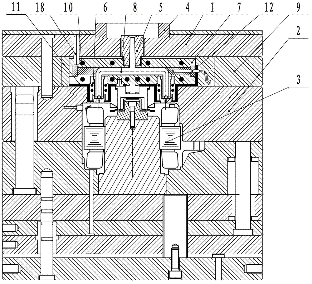
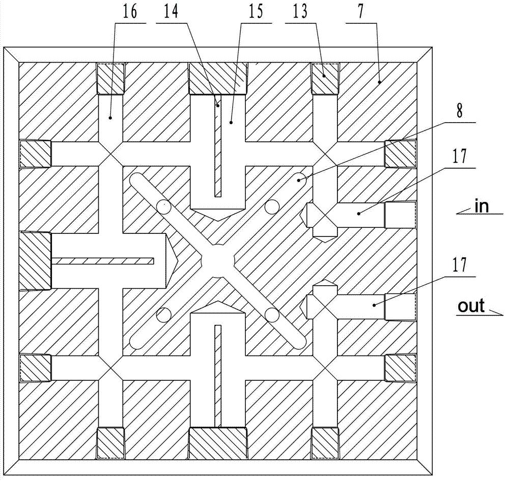
[0019] like figure 1 As shown, it includes a movable mold and a fixed mold. The fixed mold includes a fixed mold seat plate 1 and a fixed mold plate 2 for opening a stator cavity 3. It is characterized in that: the positioning ring 4 in the middle position of the fixed mold seat plate 1 and the positioning ring 4 Concentric main filling nozzle 5, fixed template 2 is provided with an upward feeding cavity, embedded in the feeding cavity is cold filling nozzle 6, a runner plate 7 is provided between the fixed mold seat plate 1 and the fixed template 2, and the flow channel The plate 7 is provided with a cold runner 8 passing through the main filling nozzle 5 and the cold filling nozzle 6, and the two sides of the runner plate 7 are provided with feet 9 higher than the runner plate 7; A cooling channel 10 is provided, and a heat insula...


PUM


Abstract

The invention provides a plastic package stator runner-free mold, and relates to a mold. In the prior art, the BMC plastic package stator and a material handle are integrated after injection molding, such that a special device is required to cut the material handle, finishing is performed, and disadvantages of more processes, time wasting, appearance affecting, environmental pollution and poor plastic package part quality are provided. The plastic package stator runner-free mold is characterized in that a middle position of a mold fixation seat plate is provided with a positioning ring and a main pouring nozzle concentrically arranged with the positioning ring, a mold fixation plate is provided with a material inlet chamber having an upward opening, a cold pouring nozzle is embedded into the material inlet chamber, a runner plate is arranged between the mold fixation seat plate and the mold fixation plate, a cold runner penetrating the main pouring nozzle and the cold pouring nozzle is arranged inside the runner plate, both sides of the runner plate are provided with a supporting foot higher than the runner plate, the runner plate and the cold pouring nozzle are provided with cooling channels, and thermal insulation layers are arranged between the cold pouring nozzle and the chamber wall of the material inlet chamber and between the runner plate and the mold fixation plate. According to the present invention, the BMC material always maintains an uncured flowing state in the runner plate, and no flowing water material is generated during an injection molding process so as to achieve material saving, energy consumption reduction and environment protection.

Description

technical field [0001] The present invention relates to a mold. Background technique [0002] The BMC (bulk molding compound) plastic sealing mold structure of the prior art, when the BMC material is injected, the BMC enters the main channel through the nozzle of the injection molding machine into the tapered channel between the plastic sealing mold runners; and then enters the mold cavity through the end of the runner. mouth; this feed mold structure injects the lower-temperature BMC mass plastic into the higher-temperature mold flow channel through high-pressure injection; resistance occurs during flow, and the BMC surface solidifies during the flow process. After injection molding, the plastic-sealed stator and handle are connected as a One piece, the material handle needs to be divided by special equipment and trimmed by grinding wheels. There are many processes, time-consuming, and it is easy to form arc-shaped pits or cracks, which will affect the appearance and the he...

Claims


Application Information

Patent Timeline
IPC IPC(8): B29C45/26B29C45/27
Inventor 娄志刚
Owner WOLONG ELECTRIC GRP CO LTD
Why Eureka
Try Eureka