Driving device for rear hub of bicycle

A driving device and bicycle technology, which is applied to axles, wheels, hubs, etc., can solve the problems of low hub applicability, insufficient sensitivity, and increased inventory

Inactive Publication Date: 2013-03-06
CHOSEN
View PDF9 Cites 10 Cited by
  • Summary
  • Abstract
  • Description
  • Claims
  • Application Information

AI Technical Summary

Problems solved by technology

[0004] (1) The ratchet 532 is supported by the spring 531 and abuts against the engaging groove 441 of the actuating ring 44, thereby driving the hub shell 40 to rotate, but the engaging groove 441 of the actuating ring 44 is square, The contact area of ​​the ratchet 532 is too small, resulting in insufficient structural strength
[0005] (2) The engaging groove 441 of the actuating ring 44 is square, so that the height of the collision of the ratchet 532 increases, that is, the volume of the actuating ring 44 is larger, resulting in an increase in the swing range of the ratchet 532 on the actuating ring 44 , resulting in insufficient sensitivity
[0006] (3), its actuating ring 44 is arranged on the fixed seat 43 of the hub shell 40, and forms axial positioning with the ratchet disc 50 through the inner wall of the hub shell 40, and the actuating ring 44 and the ratchet disc 50 still have Appropriate clearance makes the actuating ring 44 have space for axial displacement, that is, it is easy to cause wear of the ratchet plate 50 and the actuating ring 44, thereby reducing the durability of the hub structure
[0007] Four, its one-way driving mode is only suitable for general riding, and is not suitable for stunts that need to synchronously drive the wheels to produce forward and reverse actions. In this way, the additional cost of bicycles will be increased. However, due to the low applicability of the hub, the industry must simultaneously produce a variety of different styles of hubs and corresponding components, which will increase the cost of production molds and increase the lack of inventory

Method used


Image

  • Driving device for rear hub of bicycle
  • Driving device for rear hub of bicycle
  • Driving device for rear hub of bicycle

Examples


Embodiment Construction

[0067] In order to have a further understanding and understanding of the purpose, features and effects of the present invention, please cooperate with [Description of Drawings] below, and describe in detail as follows:

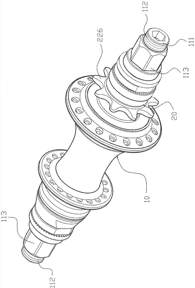
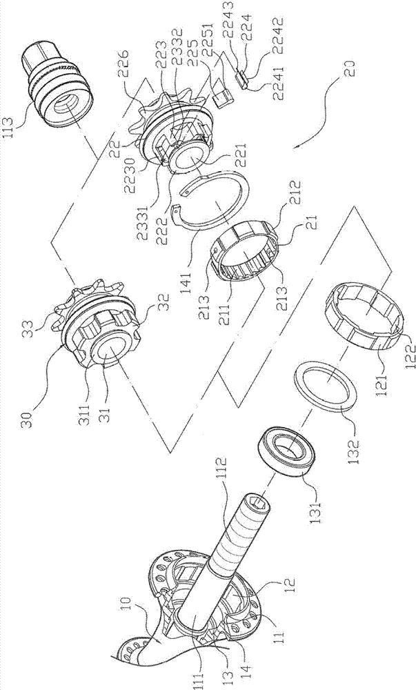
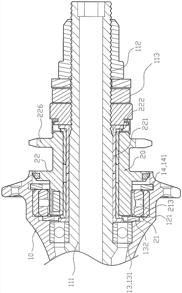
[0068] First of all, please start by figure 1 and figure 2 As shown, a driving device for a rear hub of a bicycle includes: a hub shell 10, a one-way drive assembly 20 and a two-way drive seat 30, wherein the hub shell 10 has a housing on one side Space 11, accommodating space 11 and having a mandrel 111 through the pivot, mandrel 111 is provided with a threaded section 112 at one end, threaded section 112 is provided with a locking member 113 to lock, and this accommodating space 11 is set in the inner periphery ring There are a plurality of fitting grooves 12, and the fitting grooves 12 are embedded with a fixed ring 121 in a tightly fitting manner. The fixed ring 121 is made of steel material, thereby increasing the structural strength of the hub shell 1...


PUM


Abstract

The invention relates to a driving device for a rear hub of a bicycle. The driving device comprises a hub shell, a unidirectional driving component and a bidirectional driving seat, wherein the unidirectional driving component comprises a ratchet ring and a ratchet wheel seat. A plurality of unidirectionally diagonal bevel gear sides are arranged on the inner peripheral ring of the ratchet ring, a plurality of embedded ribs are arranged on the outer peripheral ring of the ratchet ring and are embedded in fastening ribs of a fixed ring of the hub shell. A plurality of groups of combining portions oppositely arranged are arranged on the outer peripheral ring of one end of the ratchet seat, and an elastic part and a pawl abutted to the bevel gear sides are assembled on the each combining portion. The bidirectional driving seat is provided with a plurality of nested ribs arranged on an end ring, and the nested ribs of the bidirectional driving seat are nested with the fastening ribs of the fixed ring of the hub shell. The driving device in the above structure can meet requirements of riders and can be switched in unidirectional driving or bidirectional driving mode, applicability of the hub is improved, required product types of enterprises are simplified, product stock is reduced and production cost is reduced.

Description

technical field [0001] The present invention relates to a "driving device for the rear hub of a bicycle", especially by changing the combination of the ratchet ring and the ratchet seat in the one-way drive assembly, which can be applied to a bicycle with a left-hand chain or a right-hand chain. Moreover, because its structure can be converted into one-way drive or two-way drive to meet the needs of riders, it can achieve the function of improving the applicability of the hub, thereby simplifying the types of products that the industry needs to produce, thereby reducing the inventory of products, and achieving The effect of reducing production costs. Background technique [0002] There is a bicycle rear hub driving device, please use Figure 15 match Figure 16 As shown in 28, it includes: a hub shell 40 and a ratchet plate 50, wherein, a hub shell 40 is provided with an accommodating space 41, and the accommodating space 41 is pivotally provided with a mandrel 42, the mand...

Claims


Application Information

Patent Timeline
Patent Type & Authority Applications(China)
IPC IPC(8): B60B27/04B60B35/12
Inventor 陈青树
Owner CHOSEN
Why Eureka
Try Eureka