
High-speed hydraulic drill

A hydraulic drilling rig, high-speed technology, applied in drill pipe, drill pipe, earth-moving drilling, etc., can solve problems such as affecting the operator's sight, flying dust, inconvenient installation and maintenance, etc., to achieve good technical and economic value, reduce swing amount of effect

Active Publication Date: 2013-03-06
重庆勤牛工程机械有限责任公司
View PDF9 Cites 5 Cited by
  • Summary
  • Abstract
  • Description
  • Claims
  • Application Information

AI Technical Summary

Problems solved by technology

The guide frame is driven by an oil pump, and the guide frame moves up and down through the dynamic and static pulley block or the row chain variable speed. Its structure is very complicated and cannot guarantee that the guide frame moves up and down synchronously with the drill pipe.
[0004] In addition, a large amount of dust and dross will be generated during the drilling process of the drill pipe, and the existing hydraulic drilling rig does not have a dust suction device, so it is easy to appear dust flying all over the sky, which is not conducive to environmental protection, and easily affects the operator's sight
[0005] Finally, the existing lifting motor is set on the top of the drill boom, which is inconvenient for installation and maintenance. Therefore, it is urgent to solve the above technical problems

Method used


Image

  • High-speed hydraulic drill
  • High-speed hydraulic drill
  • High-speed hydraulic drill

Examples


Embodiment Construction

[0060] Below in conjunction with accompanying drawing and embodiment the present invention will be further described:

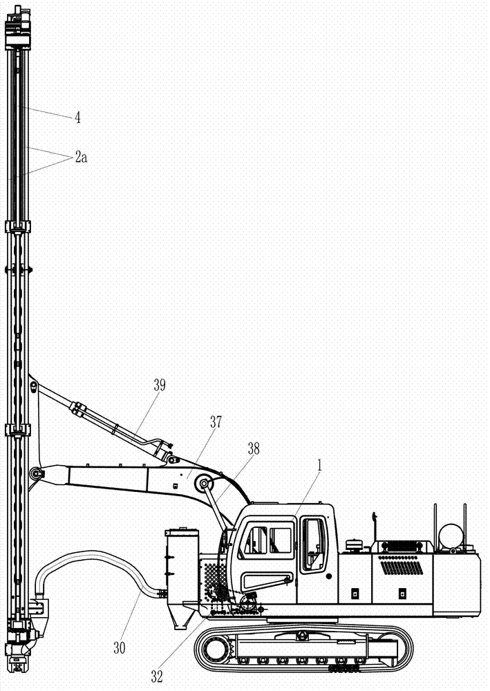
[0061] Such as Figures 1 to 11 As shown, the high-speed hydraulic drilling rig is mainly composed of a main engine 1, a drill arm 2, a positioning frame 3, a drill rod 4, a positioning sleeve 5, a box body 6, a mounting seat 7, a power box 8, a rotating motor 9, a carriage 10, and a chain 11 , lifting motor 12, guide frame 13, guide sleeve 14, guide frame follower mechanism, dust cover 24, mounting plate 25, connector 26, oil cylinder 27, first air pipe 28, primary dust collector 29, second air pipe 30 , secondary dust collector 31, screw air compressor 32, pinion 33, driving shaft 34, bull gear 35, driving sprocket 36, boom 37, boom cylinder 38, stick cylinder 39 and rubber sleeve 40 constitute. Wherein the host 1 basically adopts the existing structure, and the screw air compressor 32 is fixedly installed at the front of the host 1 .

[0062] Such as fi...


PUM

PropertyMeasurementUnit
Lengthaaaaaaaaaa

Abstract

The invention discloses a high-speed hydraulic drill. A positioning sleeve is fixedly arranged on the front part of a guide frame; a guide frame following mechanism is arranged between the guide frame and a drill boom; the left plate surface of a left vertical plate is fixed with the right end of the guide frame; the right plate surface of the left vertical plate is connected with two guide rails on the drill boom in a sliding way; a right vertical plate is positioned between the two guide rails on drill boom; the left and right vertical plates are fixedly connected with each other; the left half segment of a chain passes through a gap between the left and right vertical plates; a chain clamping plate is arranged between the left vertical plate and the left half segment of the chain; a swinging rod is arranged above the chain clamping plate; the back end of the swinging rod can be collided with the top surface of a matching part of the chain clamping plate; and a chock block is arranged between the swinging rod and the positioning frame. A drill rod is well guided through a guide sleeve on the guide frame, so that the defects of the conventional structure are overcome effectively; and the high-speed hydraulic drill has a dedusting function, and the situation of flying of dust in the air during drilling in the conventional way is avoided, so that the environment is protected, and the vision of an operator is not influenced.

Description

technical field [0001] The invention relates to a hydraulic drilling rig equipment used for drilling operations in geological exploration. Background technique [0002] High-speed hydraulic drilling rigs are mainly used for open-pit geological exploration drilling and engineering drilling that requires buried explosives during various mountain opening operations. A hydraulic drilling rig is generally composed of a main engine, a boom cylinder, a boom, a stick cylinder, a drill arm, a drill pipe, a chain, a lifting motor, a rotating motor, a power box and a carriage, etc. Compressor, electrical control system and air conditioning system. Both the drill arm and the drill rod are arranged vertically and parallel to each other, and two guide rails are arranged along the length direction on the left side of the drill arm, and the two guide rails are arranged side by side. At the same time, the upper end of the drill pipe is coaxially fixedly connected with the output shaft of t...

Claims


Application Information

Patent Timeline
IPC IPC(8): E21B19/24E21F5/00
Inventor 邹晴余光伟郑开焱谭龙
Owner 重庆勤牛工程机械有限责任公司
Learn More