Seal structure of piston type spring brake chamber

A sealing structure and brake chamber technology, applied in the direction of brake actuators, gear transmission mechanisms, mechanical equipment, etc., can solve the problems of unsatisfactory sealing effect and dustproof effect, troublesome processing and assembly, complex structure, etc., to prevent The effect of gap extrusion, simplified structure and process, and simplified process

Inactive Publication Date: 2013-03-06
宁波神丰汽车制动系统有限公司
View PDF5 Cites 0 Cited by
  • Summary
  • Abstract
  • Description
  • Claims
  • Application Information

AI Technical Summary

Problems solved by technology

[0004] The technical problem to be solved by the present invention is to overcome the insufficient sealing effect and dustproof effect of the sealing structure of the automobile piston spring brake chamber in the prior art, and many An independent sealing ring has the d

Method used


Image

  • Seal structure of piston type spring brake chamber
  • Seal structure of piston type spring brake chamber
  • Seal structure of piston type spring brake chamber

Examples


Embodiment 1

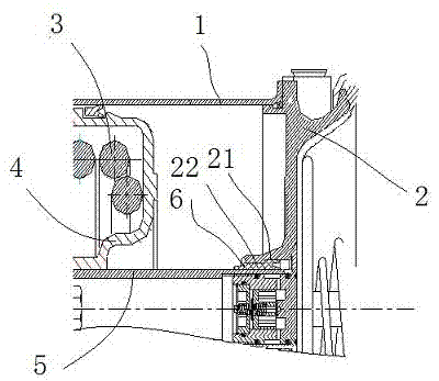
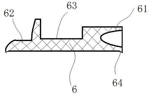
[0026] Embodiment 1: as figure 1 , 2 as shown, one A sealing structure of a piston-type spring brake chamber, including a cylinder body 1 and a middle body 2 forming a spring chamber, a spring 3 and a spring seat 4 are arranged in the spring chamber, and the spring seat 4 bears on the piston 5, and the piston 5 and the middle body 2 The middle part of the middle part is movable, and a step-shaped wide sealing groove 21 is provided at the joint between the piston 5 and the middle body 2. The middle part of the step-shaped wide sealing groove 21 is provided with an inwardly protruding shoulder 22, and the step-shaped wide sealing groove 21 is embedded with a matching sealing ring 6, and the sealing ring 6 is connected by a Y-shaped lip seal structure of the front end 61, a boot-shaped lip seal structure of the rear end 62, and a stepped 63 structure in the middle. In the composite sealing ring formed in one piece, the inner surface of the sealing ring 6 is a cylindrical stru...

Embodiment 2

[0030] Embodiment 2: The lip seal structure at the rear end of the seal ring is a J-shaped lip seal ring, the lip seal structure at the front end of the seal ring is a V-shaped lip seal ring, and the rest of the structure is the same as that in Embodiment 1; a single J In order to prevent it from falling off, the lip-shaped sealing ring of this type needs to be pressurized, and cannot be used for end face sealing or dustproof, while the composite sealing ring of the three-piece structure of the present invention can be used on the end face without pressing parts. Sealing and dustproofing, especially the dustproofing effect of the end face, is a long-standing and difficult problem for the prior art, which can be solved satisfactorily by applying the present invention.

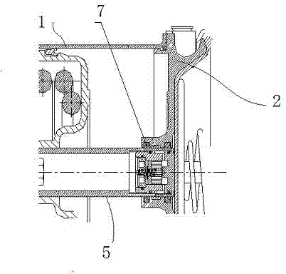
[0031] image 3 Shown is an installation structure diagram of a discrete seal ring in the prior art, and there are two O-shaped seal rings 7 at the front and rear.


PUM


Abstract

The invention discloses a seal structure of a piston type spring brake chamber in order to overcome the defects of the existing automobile piston type spring brake chamber, such as poor seal and dustproof effects, complicated processing and assembly for multiple independent seal rings and high cost. An integral composite seal ring is provided aiming at overcoming the defects in the prior art. The seal structure comprises a cylinder body and a midbody which form a spring cavity, wherein a spring and a spring base are arranged in the spring cavity, a piston is pressed against by the spring base, the piston is in movable fit with the middle part of the midbody, a wide stepped seal groove is arranged at the part of the piston, fitted with the midbody, a raised shoulder protruding inward is arranged at the middle part of the seal groove, a seal ring matched with the seal groove is embedded in the seal groove, and the seal ring is formed by connecting a lip seal structure at a front end, a lip seal structure at a rear end and a stepped structure in a middle section into a whole. The seal structure has the advantages of combination of advantages of different types of seal devices, simplification in structure and technology, convenience in processing and assembly, improvement in efficiency and reduction in cost.

Description

[0001] technical field [0002] The invention belongs to the technical field of automobile brake devices, and in particular relates to a sealing structure of a piston-type spring brake chamber. Background technique [0003] The automobile of prior art usually uses piston type spring braking device, and this braking device comprises a spring chamber and a driving chamber, and the two chambers are closed and isolated from each other, and a spring and a spring seat are arranged in the spring chamber, and the spring seat bears on the piston, and the piston It cooperates with the middle part of the middle body, and the joint between the piston and the middle body is provided with a sealing structure; the sealing structure of the prior art is to set an O-ring at the joint, and the better technical solution of the prior art is to seal the front end and the rear end of the piston. An O-ring is provided at each end. The best technical solution in the prior art is to set a sealing ring...

Claims


Application Information

Patent Timeline
IPC IPC(8): F16D65/14F16D121/04F16D125/08
Inventor 叶挺翁国畅
Owner 宁波神丰汽车制动系统有限公司
Why Eureka
Try Eureka