Integrated pneumatic shifting operation system

A technology for a pneumatic shifting and operating system, applied in the field of vehicle shifting systems, can solve the problems of high and low gear switching failure of transmission, complicated transmission structure, transmission cylinder air leakage, etc., and achieves simple and compact design structure, reduced production hours, and reduced The effect of cylinder blow-by

Active Publication Date: 2013-03-06
ZHEJIANG EASUN PNEUMATIC SCI & TECH
View PDF17 Cites 4 Cited by
  • Summary
  • Abstract
  • Description
  • Claims
  • Application Information

AI Technical Summary

Problems solved by technology

[0003] The existing shift control system is composed of a two-position five-way single H valve for controlling the transmission cylinder, a two-position two-way air circuit control valve, and a two-position three-way shift handle valve to realize transmission sub-box shifting. Although the connection of this pneumatic shift control system is simple, the user must first select the handle valve before shifting. If the user operates the shift first, and then the handle valve pre-selects, there will be air leakage inside the transmission cylinder, resulting in transmission failure. High and low gear switching failure
In this system, since there is no high-pressure gas in the transmission cylinder after the transmission is shifted into a gear, the piston cannot be kept in the high or low gear position under the thrust of the high-pressure gas, so the transmission is easy to disengage during the driving process of the vehicle.
Although it is possible to use a self-locking device on the transmission cylinder and the auxiliary box synchronizer, it complicates the structure of the transmission and increases the manufacturing cost; the original handle valves are all two-position three-way valve structures, which are used to control one end of the single H valve. At the control end, since this valve does not have a memory function, when the transmission cylinder enters the high gear or low gear, the air circuit control valve will cut off the air source, and the transmission cylinder loses high-pressure air and cannot operate in high gear or low gear. The existing technology is to add a self-locking mechanism to the shift fork shaft of the transmission cylinder. Although the effect of self-locking can also be achieved, the structure of the transmission will be complicated and the manufacturing cost will be increased.

Method used


Image

  • Integrated pneumatic shifting operation system
  • Integrated pneumatic shifting operation system
  • Integrated pneumatic shifting operation system

Examples


Embodiment Construction

[0021] For ease of understanding, the preferred embodiments of the present invention will be described in further detail below in conjunction with the accompanying drawings.

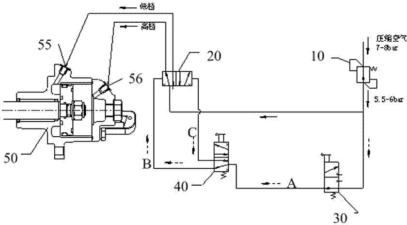
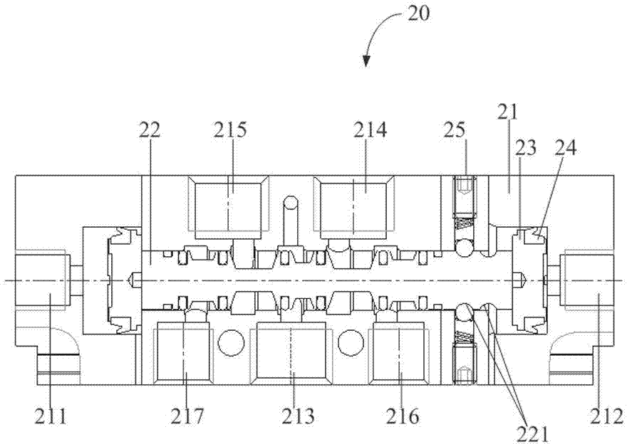
[0022] Please refer to figure 1 with figure 2 , A pneumatic shift control system for a vehicle, comprising: an air filter regulator 10, a dual-air-controlled single H valve 20, a pneumatic control valve 30, a handle valve 40 and a transmission cylinder 50, the connection relationship among them is:

[0023] The input end of the air filter regulator 10 is connected to the vehicle air source. The compressed air pressure at the input end of the air filter regulator 10 is 7-8 Bar, and the output pressure of the air filter regulator 10 is 5.5- 6Bar; in addition,

[0024] The output end of the air filter regulator 10 is respectively connected to the first input end 213 of the dual air control single H valve 20 and the input end of the air circuit control valve 30,

[0025] The output end of the gas path control v...


PUM


Abstract

The invention provides an integrated pneumatic shifting operation system, comprising an air filtering adjuster, an air way control valve, a handle valve, a double pneumatic single H valve, a speed changer cylinder and two O-rings, wherein the double pneumatic single H valve is locked on the speed changer cylinder through screws, the low shift control end outlet of the double pneumatic single H valve is hermetically connected with the low shift air inlet end of the speed changer cylinder through one O-ring, and the high shift control end outlet of the double pneumatic single H valve is hermetically connected with the high shift air inlet of the speed changer cylinder through the other O-ring. According to the integrated pneumatic shifting operation system, the structure is simple and compact, the operation is easy, the fault rate is reduced, and the service life is longer.

Description

Technical field [0001] The invention relates to a vehicle gear shifting system, in particular to a vehicle assembled pneumatic gear shifting control system. Background technique [0002] With the continuous standardization of the management of my country’s road transportation industry, the era of its efficient and lean operation has come. This requires the industry to achieve higher levels by improving transportation efficiency, reducing body weight, and reducing fuel consumption per unit of freight. Profitability level. However, road freight users require heavy trucks to have the attributes of high speed and heavy load, light weight, good fuel economy, and high attendance rate, and product demand is gradually shifting to high-end. It is expected that heavy-duty truck products equipped with high-horsepower and more gear transmissions will become mainstream, such as 16-speed, 20-speed, and 24-speed transmissions. [0003] The existing shift control system is composed of a two-p...

Claims


Application Information

Patent Timeline
Patent Type & Authority Applications(China)
IPC IPC(8): F16H61/28F16H61/40
Inventor 郑守成王吉利
Owner ZHEJIANG EASUN PNEUMATIC SCI & TECH
Why Eureka
Try Eureka