Water kinetic energy jet propulsion ventilation cooling tower

A ventilation cooling and water kinetic energy technology, applied in the field of cooling towers, can solve the problems of high operation and maintenance costs, difficulty in maintaining the cooling efficiency of cooling towers, and the decline of cooling efficiency, so as to improve unstable factors, high water removal efficiency, and small ventilation resistance Effect

Inactive Publication Date: 2013-03-06
陆洪新
View PDF5 Cites 5 Cited by
  • Summary
  • Abstract
  • Description
  • Claims
  • Application Information

AI Technical Summary

Problems solved by technology

[0002] In the past hundred years, cooling towers have been widely used in the domestic and foreign markets, and traditional counterflow packing cooling towers have been widely used, and various structural forms of packing towers have appeared; however, from the development of recent decades, all counterflow packing cooling towers The cooling efficiency is difficult to maintain, and the packing of this type of cooling tower is easy to scale when it is running, and the resistance is large. After scaling, the cooling efficiency drops significantly, power consumption, and high operation and maintenance costs.

Method used


Image

  • Water kinetic energy jet propulsion ventilation cooling tower
  • Water kinetic energy jet propulsion ventilation cooling tower
  • Water kinetic energy jet propulsion ventilation cooling tower

Examples


Embodiment Construction

[0027] Below in conjunction with specific embodiment, the technical scheme of the present invention is further explained:

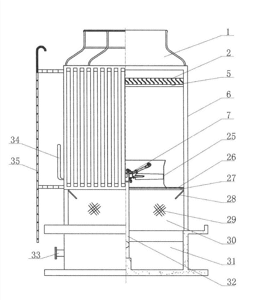
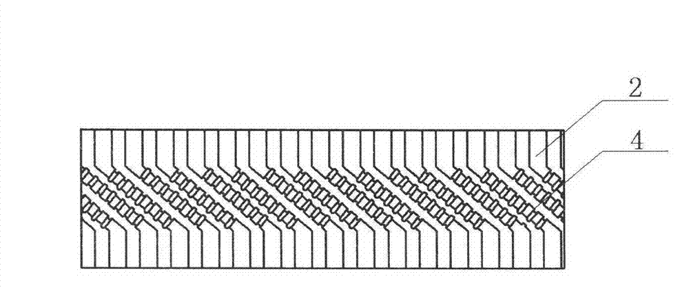
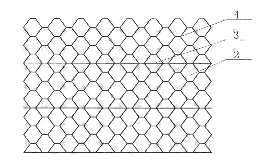
[0028] Such as figure 1 , 2, 3, 4, 5, 6, and 7, the hydrokinetic energy jet propulsion ventilation cooling tower includes: fan cylinder 1, multi-dimensional water eliminator 2, tower body 6, hydrokinetic energy jet device 7, volute type ejector 18, Air collecting cylinder 25, water spray plate 26, sump 31; air cylinder 1 is located at the top of the tower; multidimensional water eliminator 2 is located below the tower top air cylinder 1, evenly covering the plane of the entire multidimensional water eliminator frame 5, and fixed On the multi-dimensional water eliminator frame 5, the multi-dimensional water eliminator 2 is bonded into a hexagonal honeycomb structure by the multi-dimensional sheet 5 and the straight sheet 4; The outer surfaces of the front and rear sides above the tuyere 30) are covered with glass fiber reinforced plastic panels. Between ...


PUM


Abstract

The invention relates to a water kinetic energy jet propulsion ventilation cooling tower. The water kinetic energy jet propulsion ventilation cooling tower comprises an air duct, a multidimensional dehydrator, a tower body, a water kinetic energy jet device, an air collection duct, a water spray plate, a water spray grillage, an anti-splash plate, an air inlet, air guiding plates and a water collection pool, wherein the air duct is positioned at the top of the tower; the multidimensional dehydrator is positioned under the top of the tower; the water kinetic energy jet device is positioned in the middle and lower portion of the tower body and in the axial center position of the air collection duct; a jet water drop and non-saturated air combined cocurrent and countercurrent running space is between the multidimensional dehydrator and the water kinetic energy jet device; the water spray plate is arranged under the periphery of the air collection duct; the anti-splash plate is positioned under the water spray grillage; and the bottom of the body of the tower is provided with the water collection pool, and the air guiding plates are arranged at positions which are under the water spray grillage, above the water collection pool and at the middle of the tower and face the air inlet. The water kinetic energy jet propulsion ventilation cooling tower which adopts the water kinetic energy jet propulsion mode abandons a motor, a speed reducer, a filler, a countercurrent spray device and a common dehydrator, so the cooling form of the tower is optimized; the water flow can drive fan blades to rotate when the jet cooling of the water flow is carried out; and the water kinetic energy jet propulsion mode has the advantages of stable cooling effect, low maintenance cost, energy saving and environmental protection, and is suitable for medium and small cooling towers.

Description

technical field [0001] The invention relates to the technical field of cooling towers, in particular to a hydrokinetic energy jet propulsion ventilation cooling tower. Background technique [0002] In the past hundred years, cooling towers have been widely used in the domestic and foreign markets, and traditional counterflow packing cooling towers have been widely used, and various structural forms of packing towers have appeared; however, from the development of recent decades, all counterflow packing cooling towers The cooling efficiency is difficult to maintain, and the packing of this type of cooling tower is easy to scale when it is running, and the resistance is large. After scaling, the cooling efficiency drops significantly, power consumption, and high operation and maintenance costs. Contents of the invention [0003] The object of the present invention is to provide a hydrokinetic energy jet propulsion ventilation cooling tower without motor, without filler, stab...

Claims


Application Information

Patent Timeline
IPC IPC(8): F28C1/00F28F25/02F28F25/00
Inventor 吴金华陆仁德陆洪新
Owner 陆洪新
Why Eureka
Try Eureka