Electrical equipment anti-misoperation method, device and system

A technology for electrical equipment and equipment operation, applied in the direction of circuit devices, electrical components, etc., can solve the problems of difficulty in writing anti-misoperation logic, difficulty in controlling accuracy, and low reliability, so as to achieve easy adjustment of rules, reduce difficulty, Effects that are not prone to errors

Active Publication Date: 2013-03-06
ZHUHAI UNITECH POWER TECH CO LTD
View PDF6 Cites 20 Cited by
  • Summary
  • Abstract
  • Description
  • Claims
  • Application Information

AI Technical Summary

Problems solved by technology

[0017] The purpose of the present invention is to provide a method, device and system for preventing misuse of electrical equipment, which solves the problems in the prior art that the anti-misoperation logic is difficult to write, the workload is large, the accuracy is difficult to control, and the reliability is not high.

Method used


Image

  • Electrical equipment anti-misoperation method, device and system
  • Electrical equipment anti-misoperation method, device and system
  • Electrical equipment anti-misoperation method, device and system

Examples


Embodiment 1

[0048] The method for preventing misoperation of electrical equipment provided in this embodiment includes steps:

[0049] 11. Write equipment operation rule formulas that define the rules that need to be satisfied when performing each operation on each type of equipment.

[0050] According to the relevant operation management documents, equipment operating procedures, and on-site actual operation experience, the error prevention experts write the equipment operation rule formula. The equipment operation rule formula defines the rules that need to be satisfied during the closing and pulling operations of equipment such as knife switches, switches, and floor knives.

[0051] The composition and grammar of the equipment operation rule formula are:

[0052] The equipment operation rule formula is used to describe the operation rules of a certain type of equipment. The formula is divided into three parts: equipment type, operation type, and rule expression. This formula can be us...

Embodiment 2

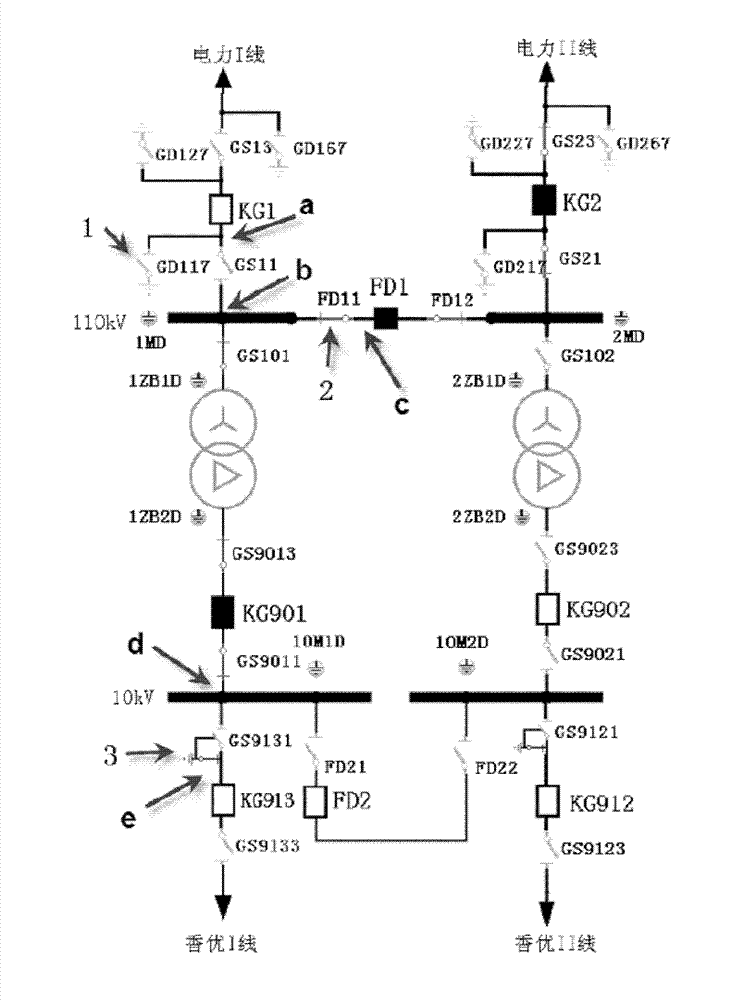
[0197] Such as image 3 As shown in the system wiring diagram, as a possible implementation mode, the anti-misoperation method provided by the present invention includes:

[0198] Step 21, write the equipment operation rule formula.

[0199] image 3 A variety of basic switch equipment and complex switch equipment are involved in the book. Taking -GD117 ground knife, -FD11 knife switch, and -GS9131 chain knife switch as examples, the method of writing the formula for the operation rules of the equipment is explained.

[0200] - The process of writing the formula for the operation rules of the GD117 ground knife is as follows:

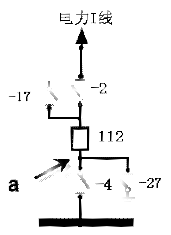
[0201] -GD117 ground knife is image 3 The equipment indicated by the middle arrow 1, the operating rules to be followed are essentially the same as figure 1 The -27 ground knife in the ground knife means that the relevant knife switches in all directions of the ground knife point are in the position, that is, when the ground knife is closed, the gr...


PUM


Abstract

The invention discloses an electrical equipment anti-misoperation method. The method comprises the following steps of: writing an equipment operation rule formulae which defines rules required to be met when every equipment carries out every operation; dividing combination-switch-class equipment into basic-switch-class equipment according to electrical properties of the combination-switch-class equipment to establish an equipment topology node table; and when an operation request is generated, computing the equipment operation rule formula of the equipment with an operation request by combination with the equipment topology node table, and returning a computed result back to an anti-misoperation main machine. The invention also provides an electrical equipment anti-misoperation device which comprises an equipment dividing module, a topology relation analyzing module, an operation rule library and an operation rule formula computation module. The invention also provides an electrical equipment anti-misoperation system which comprises the electrical equipment anti-misoperation device, a wiring diagram input device and the anti-misoperation main machine. The electrical equipment anti-misoperation method, device and system provided by the invention can effectively improve the safety and reliability of an anti-misoperation system.

Description

technical field [0001] The invention relates to the technical field of electrical control, in particular to a method, device and system for preventing misoperation of electrical equipment. Background technique [0002] Electrical equipment is divided into three states: operation, standby and maintenance. The process of changing equipment from one state to another is called switching, and the operation performed is called switching operation. By operating the isolating switch, circuit breaker, and hanging or disconnecting the ground wire, the electrical equipment is converted from one state to another or the system changes its operating mode. This operation is called switching operation. [0003] The isolating switch is the most widely used electrical appliance in high-voltage switching appliances, and it is a device that plays an isolation role in the circuit. Its working principle and structure are relatively simple, but due to the large amount of use and high reliability...

Claims


Application Information

Patent Timeline
IPC IPC(8): H02J13/00
Inventor 金述强逄凌志万利国黄建东蒋红平
Owner ZHUHAI UNITECH POWER TECH CO LTD
Why Eureka
Try Eureka