Terminal and method for terminal to transmit uplink signals
A terminal transmission and signal technology, applied in the field of communication, can solve problems such as the inability to meet the time control requirements of multiple receiving methods, and achieve the effect of improving signal transmission performance and flexibility
- Summary
- Abstract
- Description
- Claims
- Application Information
AI Technical Summary
Problems solved by technology
Method used
Image

Examples
Embodiment 1
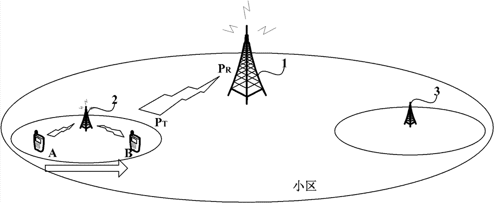
[0097] This embodiment takes figure 2 The scenario shown is an application environment of the method for transmitting an uplink signal by a mobile terminal, where the mobile terminal is a UE, and the serving base station is a micro base station 2 .
[0098] Multiple uplink power control formulas are set in the UE for each type of uplink signal, and the eNB determines the indication according to the receiving mode of the uplink signal, so that the UE selects the corresponding uplink power control formula to determine the transmit power of the uplink signal according to the indication determined by the eNB.
[0099] For example, for the uplink PUCCH, two uplink power control formulas can be set in the UE:
[0100] P T1 =min{P max , P 0,1 +PL DL,1 +Δ Format,1 +δ 1} (41)
[0101] P T2 =min{P max , P 0,2 +PL DL,2 +Δ Format,2 +δ 2} (42)
[0102] Among them, the uplink power control formula (41) is for the UE to determine the transmission power P of the uplink PDCCH wh...
Embodiment 2
[0116]Similar to Embodiment 1, multiple uplink power control formulas are set for each type of uplink signal in the UE, but each uplink power control formula only performs independent closed-loop control, and other variables of each uplink power control formula do Same configuration.
[0117] For example, for the uplink PUCCH, use the following uplink power control formula to determine the transmit power of the uplink PUCCH:
[0118] P T1 =min{P max , P 0 +PL DL +Δ Format +δ 1} (71)
[0119] P T2 =min{P max , P 0 +PL DL +Δ Format +δ 2} (72)
[0120] From the above uplink power control formula (71) and uplink power control formula (72), it can be seen that for different uplink power control formulas P 0 ,Δ Format Do the same configuration, and let UE use the same path loss estimation PL DL , but each process performs closed-loop power control independently, that is, δ 1 and δ 2 Perform independent adjustments, and adjust δ in each uplink power control formula ...
Embodiment 3
[0130] This embodiment is further simplified compared to the previous two embodiments. In this embodiment, each UE is provided with multiple uplink power control formulas. Among these uplink power control formulas, one uplink power control formula is used as a reference, and other uplink power control formulas are obtained by adding a compensation value to the reference. The offset is obtained.
[0131] For example, two uplink power control formulas are set in the UE for the uplink PUCCH, and one of the uplink power control formulas is used as a reference, such as the uplink power control formula (1). Assume that the transmit power calculated by using the benchmark, that is, the uplink power control formula (1) is P T1 , then another uplink power control formula is to add a compensation value on the basis of uplink power control formula (1), namely
[0132] P T2 =P T1 +Δ procedure . where Δ procedure It is the compensation value, that is, the offset value. This compens...
PUM
 Abstract
Description
Claims
Application Information
 - R&D
- Intellectual Property
- Life Sciences
- Materials
- Tech Scout
- Unparalleled Data Quality
- Higher Quality Content
- 60% Fewer Hallucinations
Browse by: Latest US Patents, China's latest patents, Technical Efficacy Thesaurus, Application Domain, Technology Topic, Popular Technical Reports.
© 2025 PatSnap. All rights reserved.Legal|Privacy policy|Modern Slavery Act Transparency Statement|Sitemap|About US| Contact US: help@patsnap.com