Method and apparatus for reliably laser marking articles

A technology for marking items, applied in the direction of welding/welding/cutting items, manufacturing tools, metal processing, etc.

Inactive Publication Date: 2013-03-06
ELECTRO SCI IND INC
View PDF8 Cites 15 Cited by
  • Summary
  • Abstract
  • Description
  • Claims
  • Application Information

AI Technical Summary

Problems solved by technology

The markings should be durable and have a commercially desirable appearance

Method used


Image

  • Method and apparatus for reliably laser marking articles
  • Method and apparatus for reliably laser marking articles
  • Method and apparatus for reliably laser marking articles

Examples


Embodiment Construction

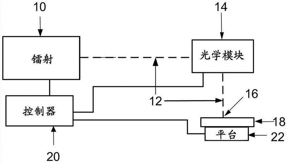
[0031] The present invention features visible markings of various optical densities and colors to durably, selectively, predictably, and repeatably mark anodized aluminum articles. Advantageously, it enables said marking to appear at or near the surface of the aluminum, leaving the anodic oxidation layer substantially intact to protect the surface and said marking. Marks made in this way are called interlayer marks because they are made at or on the surface of the aluminum below the oxide layer forming the anodization. Ideally, the oxide remains intact after the mark is added to protect the mark and provide a mechanically adjacent surface between adjacent marked and non-marked areas. Furthermore, the marks should be able to be produced reliably and reproducibly, meaning that if a mark is desired with a specific color and optical density, it is known that when the anodized aluminum is processed with a laser processing system it will produce a predetermined set of results. Lase...


PUM


Abstract

The invention is a method and apparatus for creating marks 194 on an anodized aluminum specimen 190 with selectable color and optical density. The method includes providing a laser marking system 148 having a laser 150, laser optics 154 and a controller 160 operatively connected to said laser 150 to control laser pulse parameters. The laser marking system 148 is directed to produce laser pulses 152 having laser pulse parameters associated with the desired color and optical density in the presence of a fluid 168 directed to the surface of the anodized aluminum specimen 158 while marking.

Description

[0001] The present invention is a continuation of part of the application No. 12 / 704,293 filed on February 11, 2010. technical field [0002] The present invention relates to laser marking of anodized articles with a laser processing system. In particular, laser processing systems are used to mark anodized items in a durable and commercially desirable manner. Specifically, it relates to uniquely characterizing the interaction between ultraviolet, visible, and infrared wavelength laser pulses and anodized articles to reliably and reproducibly establish in the presence of a fluid having a predetermined color and Permanent mark of optical density. Background technique [0003] Products on the market often require some form of marking on them for commercial, regulatory, decorative or functional purposes. Desirable marking properties include consistent appearance, permanence, and ease of application. Appearance refers to the ability to reliably and repeatably present a mark in...

Claims


Application Information

Patent Timeline
Patent Type & Authority Applications(China)
IPC IPC(8): B23K26/18B23K26/36B23K26/04H01S3/10B23K103/10
CPCB23K26/367B23K26/063B23K26/0807B23K26/046B23K2201/34B23K26/18B23K26/0853B23K26/401B23K26/4085B23K2203/10B23K26/40B23K26/0622B23K26/082B23K26/364B23K2101/35B23K2103/10B23K2103/16B23K26/073B23K26/08B23K26/062
Inventor 张海滨格兰·西门森派崔克·李奥纳德
Owner ELECTRO SCI IND INC
Why Eureka
Try Eureka