Drum type electro-osmosis dehydrator for reducing power consumption by means of a narrow distance between a positive electrode and a negative electrode

A dehydrator and electro-osmosis technology, applied in the direction of dehydration/drying/concentrated sludge treatment, filtration separation, semi-permeable membrane separation, etc., can solve the problems of extending the distance between positive and negative electrodes, filter bag consumables, and hindering power supply, etc. To achieve the effect of narrowing the distance

Active Publication Date: 2013-03-06
FINEMART CO LTD
View PDF11 Cites 9 Cited by
  • Summary
  • Abstract
  • Description
  • Claims
  • Application Information

AI Technical Summary

Problems solved by technology

However, the problem with the traditional electro-osmotic dehydrator is that there is a filter bag between the positive and negative electrodes, which hinders the power supply and distances the distance between the positive and negative electrodes.
[0007] Another problem is that the filter pack is a consumable product and needs to be replaced with a new one after 6 to 9 months of use

Method used


Image

  • Drum type electro-osmosis dehydrator for reducing power consumption by means of a narrow distance between a positive electrode and a negative electrode
  • Drum type electro-osmosis dehydrator for reducing power consumption by means of a narrow distance between a positive electrode and a negative electrode
  • Drum type electro-osmosis dehydrator for reducing power consumption by means of a narrow distance between a positive electrode and a negative electrode

Examples


Embodiment Construction

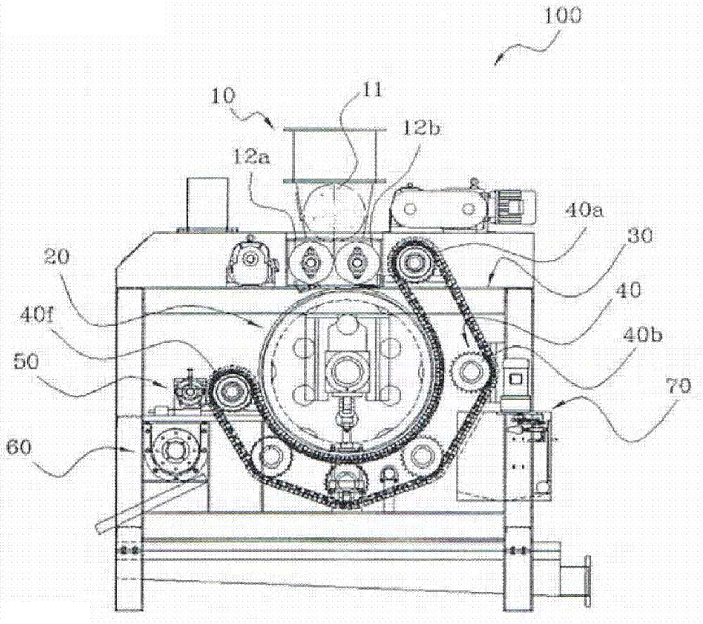
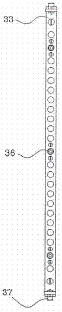
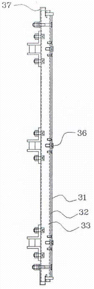
[0026] The drum-type electroosmotic dehydrator for saving electricity by reducing the distance between the positive electrode and the negative electrode will be described in detail below with reference to the accompanying drawings according to an embodiment of the present invention. figure 1 It is a front view of the electroosmotic dehydrator of the present invention. figure 2 It is the figure of the crawler belt of the electroosmosis dehydrator of the present invention, image 3 and Figure 4 It is the figure of the caterpillar part of the electroosmosis dehydrator of this invention.

[0027] refer to Figure 1 to Figure 4 , by reducing the distance between the positive and negative poles, the drum type electro-osmosis dehydrator (100) that realizes power saving includes a sludge supplier (10), a drum (20), a caterpillar (30), and an idler chain Wheels (Idle Sprocket; 40).

[0028] The sludge supplier (10) is located above the center of the electroosmotic dehydrator (100...


PUM


Abstract

The present invention relates to an electro-osmosis dehydrator. The electro-osmosis dehydrator comprises: a sludge supply part provided on a central upper portion, the sludge supply part including a rotating part and two rollers provided under the rotating part; a drum to which DC power having one polarity is applied to a cylindrical inner surface thereof that is rotated along a shaft, the drum being provided under the sludge supply part so as to receive sludge; a caterpillar part including a power applying part orbitally operated at a position spaced a predetermined distance apart from the drum so as to apply DC power having a polarity opposite to that applied to the drum, a filter cloth provided under the power applying part, caterpillars having a plurality of holes and being provided under the filter cloth, a vinyl part disposed between the filter cloth and the caterpillars so as to prevent the sludge from leaking between the caterpillars, and a chain provided under the caterpillar; and a plurality of idle sprocket parts provided in spaces between the caterpillar part to contact the chain, thereby operating the caterpillar parts. According to the present invention, the filter cloth between a positive electrode and a negative electrode may be removed so as to narrow a distance between the positive electrode and the negative electrode, thereby reducing power consumption.

Description

technical field [0001] The invention relates to a drum-type electro-osmosis dehydrator, in particular to a drum-type electro-osmosis dehydrator which saves electricity by reducing the distance between positive and negative electrodes. Background technique [0002] Generally, an electroosmotic dehydrator is a device that can be connected to a DC power supply to form an electromagnetic field required to remove moisture combined with sludge using electrophoresis, and remove the moisture contained in sludge through its voltage difference. [0003] This electrophoretic electroosmotic dehydrator is known as "electroosmotic dehydrator (Korean application number: 10-2004-7759)"; "phase control type electric dehydrator (Korean application number: 10-2005-9928)"; "Electro-osmotic dehydration machine (Korean application number: 10-2007-46494)"; "phase-controlled electrophoretic electro-osmotic dehydration machine using three-phase AC power supply (Korean application number: 10-2008-449...

Claims


Application Information

Patent Timeline
Patent Type & Authority Applications(China)
IPC IPC(8): C02F11/12
CPCC02F1/4698C02F2201/4617C02F11/006C02F11/123B01D61/427C02F11/15B01D35/06C02F2201/002Y02W10/20B01D35/16C02F2303/16
Inventor 李相俊
Owner FINEMART CO LTD
Why Eureka
Try Eureka