
High energy storage capacitor by embedding tunneling nano-structures

An energy storage device and tunneling technology, applied in capacitors, fixed capacitors, electrolytic capacitors, etc., can solve the problems of high battery degradation rate, slow charging and discharging performance, etc., and achieve low aging over time, extended life, and high storage capacity Effect

Inactive Publication Date: 2013-03-06
THE BOARD OF TRUSTEES OF THE LELAND STANFORD JUNIOR UNIV
View PDF6 Cites 6 Cited by
  • Summary
  • Abstract
  • Description
  • Claims
  • Application Information

AI Technical Summary

Problems solved by technology

Slow ion migration in batteries also leads to slow charge and discharge performance
Further, the dependence of existing batteries on ion migration leads to a high degradation rate of the battery

Method used


Image

  • High energy storage capacitor by embedding tunneling nano-structures
  • High energy storage capacitor by embedding tunneling nano-structures
  • High energy storage capacitor by embedding tunneling nano-structures

Examples


Embodiment Construction

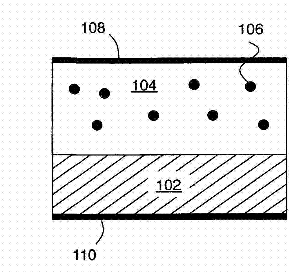
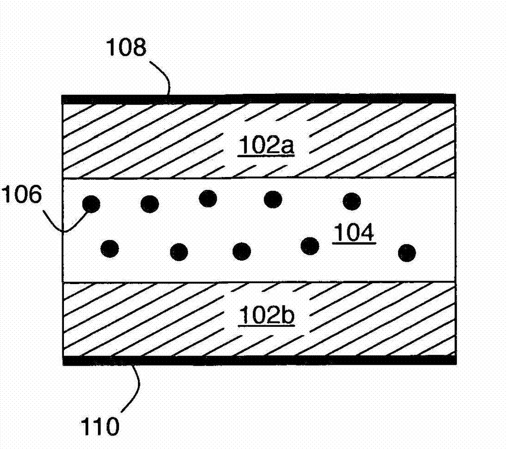
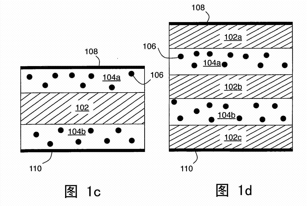
[0030] Figure 1a -d shows several embodiments of the invention. In general terms, embodiments of the present invention are energy storage devices that include a first electrode, a second electrode, one or more active layers (or active regions), and one or more barrier layers. The active layer and the barrier layer are interposed between the electrodes. The active layer has inclusions disposed in the active layer matrix so that electrons can flow to or from the inclusions through tunneling of the active layer matrix. The barrier layer substantially prevents tunneling of electrons across the barrier layer (and also substantially blocks all other DC current flow). Such devices can store energy by creating a charge gap with inclusions, and can provide energy by using this charge gap as a source of energy.

[0031] exist Figure 1a In the example of , barrier layer 102 and active layer 104 are sandwiched between electrodes 108 , 110 . One of the inclusions of the active layer 1...


PUM


Abstract

In an All-Electron Battery (AEB), inclusions embedded in an active region between two electrodes of a capacitor provide enhanced energy storage. Electrons can tunnel to / from and / or between the inclusions, thereby increasing the charge storage density relative to. a conventional capacitor. One or more barrier layers is present in an AEB to block DC current flow through the device. The AEB effect can be enhanced by using multi-layer active regions having inclusion layers with the inclusions separated by spacer layers that don't have the inclusions. The use of cylindrical geometry or wrap around electrodes and / or barrier layers in a planar geometry can enhance the basic AEB effect. Other physical effects that can be employed in connection with the AEB effect are excited state energy storage, and formation of a Bose-Einstein condensate (BEC).

Description

technical field [0001] The present invention relates to energy storage. Background technique [0002] Energy storage is a vital component of a large number and variety of electronic devices, especially mobile devices and electric or hybrid vehicles. Energy storage devices are based on a variety of physical effects. For example, electric fields can be used to store energy in capacitors, and chemical reactions, including ion movement, can be used to store energy in batteries. However, energy storage in capacitors may be limited by device geometry (for example, 2-D capacitor plates have limited area), and batteries may have slow response times due to the inherent ion motion in electrochemical reactions. [0003] Battery powered devices, such as hybrid or electric vehicles, are often performance limited by the relatively low energy stored by the battery per unit weight. Batteries have a low storage density due to the low voltage generated by the electrochemical reactions and ...

Claims


Application Information

Patent Timeline
Patent Type & Authority Applications(China)
IPC IPC(8): H01G9/02H01G9/048
CPCY02T10/7022H01G9/048H01G9/02H01L28/40H01L29/127B82Y10/00H01G4/33H01G11/26H01G11/28H01G11/52H01G4/06H01G4/085Y02T10/70Y02E60/13
Inventor T·P·霍姆F·B·普林兹P·B·范斯多科姆
Owner THE BOARD OF TRUSTEES OF THE LELAND STANFORD JUNIOR UNIV
Learn More