
A high-frequency vibration casting mold and casting process for the broken wall of the cone sand making machine

A conical sand making machine and high-frequency vibration technology, which is applied in the direction of manufacturing tools, casting molding equipment, casting molds, etc., can solve the problems of high crushing cost, poor feeding effect, poor casting density, etc., to avoid Damage phenomenon, good feeding effect, and improved impact resistance

Active Publication Date: 2015-10-21
ZHEJIANG SHUANGJIN MACHINERY HLDG
View PDF13 Cites 0 Cited by
  • Summary
  • Abstract
  • Description
  • Claims
  • Application Information

AI Technical Summary

Problems solved by technology

[0006] The common disadvantages of the above-mentioned background technologies are: first, poor wear resistance, resulting in high crushing costs; second, poor feeding effect, poor casting density, and easy damage

Method used


Image

  • A high-frequency vibration casting mold and casting process for the broken wall of the cone sand making machine
  • A high-frequency vibration casting mold and casting process for the broken wall of the cone sand making machine
  • A high-frequency vibration casting mold and casting process for the broken wall of the cone sand making machine

Examples


Embodiment 1

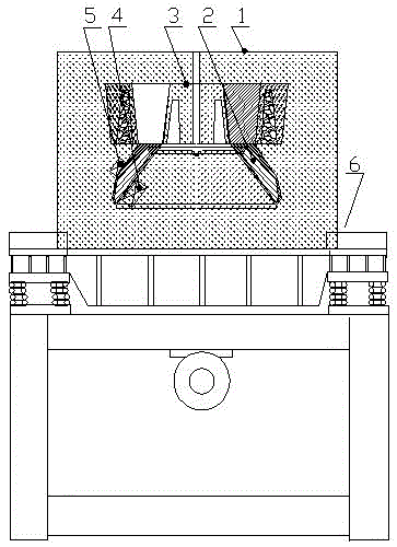
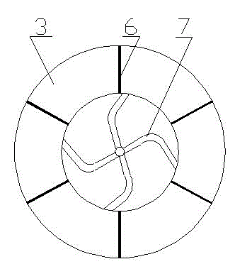
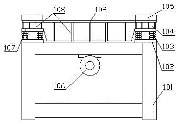
[0015] Embodiment 1: with reference to attached Figure 1-3 . A conical sand making machine broken wall high-frequency vibration casting mold, the sand box 1 is located on a high-frequency vibration platform, the height of the broken wall forming cavity 2 in the sand box 1 is smaller than the height of the pouring riser 3 or the volume of the forming cavity 2 is smaller than the pouring The volume of the riser 3 is provided with a plurality of riser spacers 6 around the pouring riser 3 . The inner and outer walls of the crushing wall molding cavity 2 are provided with a plurality of built-in cold irons 4 and external cold irons 5 . The pouring riser 3 is provided with a plurality of runners 7 . The four corners of the rectangular support 101 of the high-frequency vibration platform are respectively provided with one or more compression springs 103, the compression springs 103 are provided with a pressure-bearing vibration platform 104, and the high-frequency vibrator 106 is ...

Embodiment 2

[0016] Example 2: On the basis of Example 1, a conical sand making machine broken wall high-frequency vibration pouring mold casting process, the sand box 1 is located on the high-frequency vibration platform, and the height of the broken wall molding cavity 2 in the sand box 1 is Less than the height of pouring riser 3 or the volume of molding cavity 2 is smaller than the volume of pouring riser 3, pour high chromium cast iron into the broken wall molding cavity 2 and pouring riser 3, then perform high-frequency vibration on the high-frequency vibration platform, and cool After that, a high-density high-chromium cast iron crushing wall can be obtained. The weight of the high chromium cast iron broken wall is less than that of the pouring riser. A circle of the pouring riser 3 is provided with a plurality of riser spacers 6 . The vibration frequency of the high-frequency vibration platform is greater than 2000 Hz / min, the amplitude is less than 1.3 mm, and the vibration time ...


PUM


Abstract

The invention relates to a high-frequency vibration casting mold of a conical sand maker breaking wall and a casting process capable of achieving the effect of no shrinkage cavity and effectively improving the cast density during casting feeding of the conical sand maker breaking wall. The high-frequency vibration casting mold is characterized in that a sand box is located on a high-frequency vibration platform; and the height of a breaking wall forming mold cavity in the sand box is smaller than the height of a casting riser or the volume of the forming mold cavity is smaller than the volume of the casting riser. The casting process comprises the following steps: casting high chromium cast iron into the breaking wall forming mold cavity and the casting riser, then carrying out high-frequency vibration on the high-frequency vibration platform, and cooling to obtain the high chromium cast iron breaking wall with a high density. The high-frequency vibration casting mold and the casting process have the advantages that firstly, the wear resistance of the high chromium cast iron breaking wall is effectively improved, and the sand making cost is greatly reduced; secondly, the feeding effect is good, the cast is high in density, and the occurrence of damage phenomenon is avoided; and thirdly, the wear resistance, the shock resistance and the service life are increased by nearly 5 times, and unexpected technical effects are achieved.

Description

technical field [0001] The present invention relates to a conical sand making machine broken wall high-frequency vibration casting mold and casting process that can obtain no shrinkage cavity and effectively improve the casting density during the casting feeding process of the broken wall of the cone sand making machine. It belongs to the field of foundry. Background technique [0002] CN102380579A, titled "a casting method for crushing walls or rolling mortar walls", including the following steps: 1) Preparing metal molds: designing the inner and outer metal mold shapes according to the shape of the casting, leaving sand-covered and machining allowances during the design, and using ordinary carbon Plain steel molding, formed by machining; 2) Preparation of sand covering: sand covering is composed of the following raw materials in parts by weight, 80-90 parts of standard sand, 3-5 parts of montmorillonite, 2-3 parts of attapulgite 1-2 parts of iron oxide, 3-5 parts of water...

Claims


Application Information

Patent Timeline
Patent Type & Authority Patents(China)
IPC IPC(8): B22C9/02B22D27/08
Inventor 胡祖尧
Owner ZHEJIANG SHUANGJIN MACHINERY HLDG
Learn More