Direct-driving type bogie structure

A bogie, direct-drive technology, applied in the direction of the bogie, the device for lateral relative movement between the chassis and the bogie, and the components of the railway car body, etc., can solve the problem of short service life, large wheelbase and poor reliability etc. to achieve the effect of improving ride comfort, reducing additional stiffness, and optimizing stress

Active Publication Date: 2013-03-13
CRRC NANJING PUZHEN CO LTD
View PDF6 Cites 18 Cited by
  • Summary
  • Abstract
  • Description
  • Claims
  • Application Information

AI Technical Summary

Problems solved by technology

It can be seen that the comparison document realizes the flexibility of the bogie through the rubber joints at the hinges. Different rubber joints are designed according to the bogies of different models. This structure uses rubber joints to realize the torsion. Due to temperature changes, the performance parameters of the rubber joints often differ greatly from the design values. At the same time, the rubber is prone to aging and cracking, with poor reliability and relatively short service life.
Moreover, the motor is still installed on the bogie, and the wheelbase has a large wheelbase, which fails to significantly improve the performance of the bogie

Method used


Image

  • Direct-driving type bogie structure
  • Direct-driving type bogie structure
  • Direct-driving type bogie structure

Examples


Embodiment 1

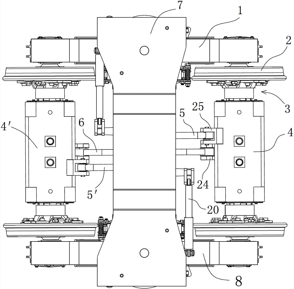
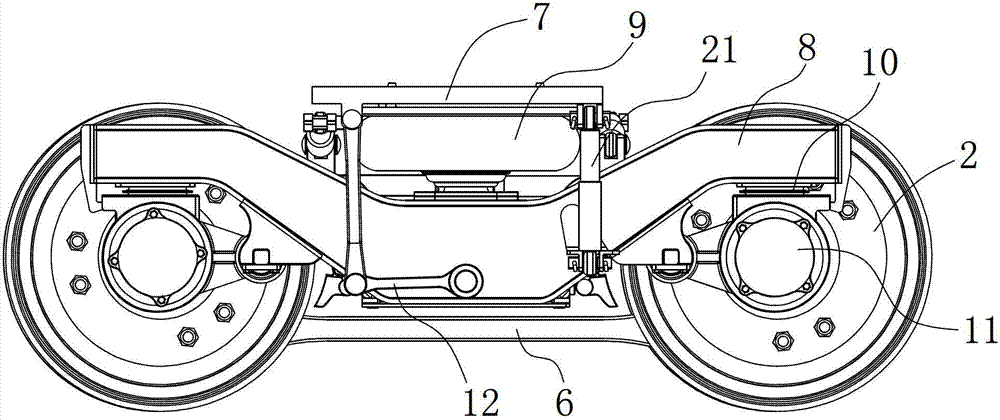
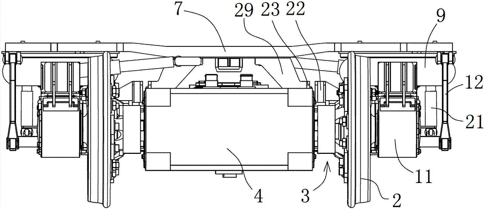
[0028] Such as Figure 1 to Figure 10 As shown, the direct drive bogie of this embodiment includes: a bogie frame, two permanent magnet motors 4 (4') located on the front and rear sides of the bogie frame, and an air spring 9 arranged above the bogie frame , The front and rear wheel sets are arranged under the bogie frame. The bogie frame has a left frame 1 and a right frame 8. The axle of the wheel set passes through the central through hole provided by the permanent magnet motor 4 (4'). The permanent magnet motor The output shafts at both ends of the 4 (4') are respectively fixed to the two wheels 2 of the wheel set by the elastic transmission device 3, so that the permanent magnet motor 4 (4') is suspended between the wheel sets, and the two permanent magnet motors 4 (4') ) Are connected by a longitudinal connecting rod 6. A transition plate 7 for fixed connection with the vehicle body is provided across the air spring 9 and a traction rod seat 18 is installed at the center ...

Embodiment 2

[0037] The structure of the second embodiment is the same as that of the first embodiment. The difference is that the parameters of the flexible beam are different. In this case, d=38mm, L=120mm; Z=25mm, the steel plate length is 1100mm, the angle between the steel plates α=66 degrees, and the steering The frame wheelbase is 1800mm and the steel plate material is P275. The torsional stiffness of the frame is 0.315 MN.m / rad and the shear stiffness is 102.98 MN.m / rad. The smaller torsional stiffness can adapt to worse lines, and the larger shear stiffness can Ensure the higher serpentine stability of the vehicle.


PUM


Abstract

The invention relates to a direct-driving type bogie structure. A permanent magnetic motor is elastically suspended by an elastic driving device, so that torque can be transferred, the transmission efficiency is improved, the weight of a driving mechanism is reduced; and traction force and braking force are directly transmitted to a vehicle body and are not transmitted through a bogie frame, so that the stressing condition of the a bogie frame is optimized, the length of a traction pull rod is not limited by the bogie frame structure, the traction pull rod can be longer, diallel additional rigidity caused by the traction pull rod is reduced, and the taking comfort of a vehicle is improved. The motor is suspended between wheel pairs, so that the axle distance is reduced, the bogie can pass a shorter curve, has higher critical speed, and has good submissiveness to unevenness of a road.

Description

Technical field [0001] The invention relates to a direct-drive bogie, belonging to the technical field of rail vehicle bogies. Background technique [0002] Traditional bogies generally use H-shaped frames, rigid beams, and rely on a series of vertical flexible suspensions to overcome the torsion and unevenness of the line. When the wheel sets travel to a gentle curve, the rigid frame will locally bear relatively large torque due to the super high curve track. When the vehicle speed is high, the connection between the frame and the first series of vertical flexible suspension will also receive a greater impact; in the traditional bogie structure design, the motor is installed on the frame to allow the motor and wheelset The dynamic disturbance and transmission torque need to be set up with complicated couplings and gearboxes. This kind of bogie has a complex structure and low production efficiency, and the wheelbase of the bogie is large and heavy, which makes the bogie It is di...

Claims


Application Information

Patent Timeline
Patent Type & Authority Applications(China)
IPC IPC(8): B61F5/50B61F5/12
Inventor 楚永萍唐永明冯遵委胡定祥周睿
Owner CRRC NANJING PUZHEN CO LTD
Why Eureka
Try Eureka