A suspension bridge scatter cable saddle

A technology of loose cable saddles and suspension bridges, applied in bridges, bridge parts, bridge construction, etc., can solve the problems of large amount of excavation for anchorage 09, increase the construction cost of suspension bridges, restrict layout, etc., and achieve the advantages of anchorage installation and stable floating , to ensure the effect of reliability and stability

Active Publication Date: 2015-07-29
SICHUAN DEPT OF TRANSPORTATION HIGHWAY PLANNING PROSPECTING & DESIGN RES INST +1
View PDF7 Cites 0 Cited by
  • Summary
  • Abstract
  • Description
  • Claims
  • Application Information

AI Technical Summary

Problems solved by technology

However, since the above-mentioned scatter saddle only has a single downward divergent structure in the vertical direction, the component force of the cable strand 06 in the vertical direction is always downward, and the downward component force needs to rely on sliding or swinging. base 07 for balancing (eg Figure 4 shown), in this case, it is necessary to design and process the base while designing and processing the loose cable saddle, which will inevitably increase the construction cost of the suspension bridge; in addition, because there is only a single downward divergent structure in the vertical direction, the entire anchorage body 08 The lower part of the anchorage body 08 not only limits the arrangement of other structures under the anchorage body 08, but also will inevitably cause a large amount of excavation of the anchorage body 09 (such as Figure 5 shown), further greatly increasing the construction cost of the suspension bridge

Method used


Image

  • A suspension bridge scatter cable saddle
  • A suspension bridge scatter cable saddle
  • A suspension bridge scatter cable saddle

Examples


Embodiment 1

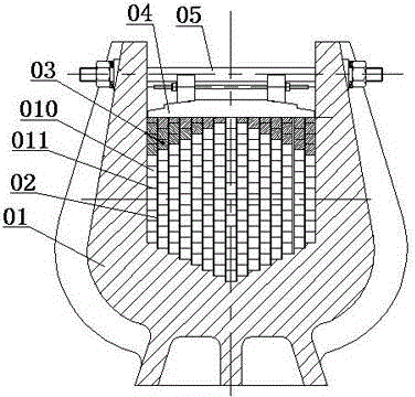
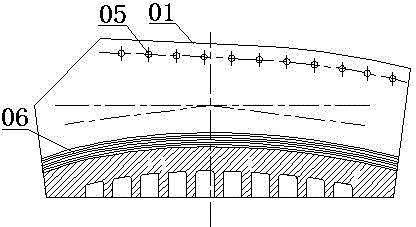
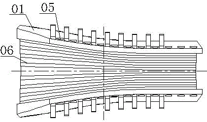
[0030] see Figure 6 to Figure 10 : The present invention comprises a saddle body 1 and a compression beam 4. The saddle body 1 has a saddle groove in the shape of "U", and the end of the saddle groove facing the anchorage 12 is an outwardly expanded arc-shaped conical surface structure; in the saddle groove of the saddle body 1, a plurality of partitions 2 are arranged at intervals, adjacent to each other. The middle and lower part of the partition 2 is provided with a plurality of layered plates 17 at intervals by welding, and the middle and upper parts of adjacent partitions 2 are provided with a plurality of corresponding limiting grooves 9 at intervals, and the limiting grooves 9 are embedded with limiting pins 8 , the layered plate 17, the limit pin 8 and the partition plate 2 divide the saddle groove of the saddle body 1 into several partition holes 16, and each partition hole 16 is used as a cable strand 7 that is penetrated into a dispersed main cable; The saddle gro...

Embodiment 2

[0033] The other structure of this embodiment is the same as that of Embodiment 1, the difference is that a plurality of corresponding limiting grooves are arranged at intervals between adjacent partitions, that is, a plurality of corresponding limiting grooves are arranged at intervals between adjacent partitions. The middle and lower parts of the adjacent partitions are also provided with a plurality of corresponding limiting grooves at intervals, and the limiting pins are embedded in the limiting grooves. The limiting pins and the partitions divide the saddle groove of the saddle body into several partitions. Each spacer hole is used to penetrate a strand of the dispersed main cable, and the limit pin has both a layering effect and a limit effect here.


PUM


Abstract

The invention discloses a splay saddle of a suspension bridge. The splay saddle comprises a saddle body and a compression beam, wherein the saddle body comprises a U-shaped saddle groove; one end of the saddle groove faces to an anchorage and is in an externally expanded arc-shaped conical surface structure; a plurality of baffles are arranged in the saddle groove of the saddle body at intervals; one end of the compression beam faces to the anchorage and is in an externally expanded arc-shaped conical surface structure; the compression beam is fixed on the top of the saddle body through a plurality of fastening bolts; the top of the saddle groove of the saddle body is plugged by the compression beam; and one end of the whole splay saddle faces to the anchorage and is in a horn mouth structure expanding from inside to outside gradually. With the adoption of the splay saddle of the suspension bridge, symmetrical splay structures are ensured to be arranged in a horizontal direction and a vertical direction of the splay saddle under the premise that a cable strand can be easily and conveniently anchored, so that not only is reliable and stable floating realized, but also the excavated volume on the anchorage is low, and the manufacturing cost of the suspension bridge is effectively reduced.

Description

technical field [0001] The invention relates to a main cable erecting member of a suspension bridge, in particular to a loose cable saddle of a suspension bridge. Background technique [0002] The main load-bearing component of the suspension bridge is the main cable, and the reliability of the anchorage of the main cable on the anchorage directly determines the safety of the suspension bridge. In order to ensure the anchoring reliability of the main cable on the anchorage, it is usually realized by enlarging the anchorage area of ​​the main cable, that is, the main cable is divided into several divergent strands by using loose cable saddles, and each strand is Anchoring on the anchorage. [0003] see Figure 1 to Figure 5 : The traditional loose cable saddle is mainly composed of a saddle body 01 and a compression beam 04; the saddle body 01 has a saddle groove in a "U" shape, and the end of the saddle groove facing the anchor is an outwardly expanding arc-shaped conical s...

Claims


Application Information

Patent Timeline
Patent Type & Authority Patents(China)
IPC IPC(8): E01D19/14
Inventor 蒋劲松唐明刘振宇赵鹏贤林智敏刘昌华
Owner SICHUAN DEPT OF TRANSPORTATION HIGHWAY PLANNING PROSPECTING & DESIGN RES INST
Why Eureka
Try Eureka