
Axial flow type fluid driving device

A fluid-driven, axial-flow technology that is applied to parts of pumping devices for elastic fluids, axial-flow pumps, liquid fuel engines, etc., can solve resonance phenomena, large operating noise, and increase the load on the drive shaft of the device, etc. problem, to achieve the effect of increasing the passing flow and improving the conveying efficiency

Active Publication Date: 2013-03-13
ZHEJIANG HONGYOU AIR COMPRESSOR MFG
View PDF7 Cites 9 Cited by
  • Summary
  • Abstract
  • Description
  • Claims
  • Application Information

AI Technical Summary

Problems solved by technology

However, the above-mentioned integrated axial flow drive device has obvious defects, which are mainly reflected in three aspects: 1) Due to the scheme that the root of each blade is connected to the hub, the cross section of the axial inlet passage near the hub is affected by the blade It is too dense and blocked, which hinders the passage of more fluids, or reduces the delivery efficiency of the device. This shortcoming is particularly prominent in small axial flow fans and axial flow vane pumps; 2) due to The root of each blade is connected to the hub, resulting in a larger overall mass of the device, especially a larger moment of inertia of the entire device, and a larger moment of inertia of the device under the same operating conditions, resulting in an increase in the size of the device. The burden on the drive shaft, which is very easy to cause fatigue fracture of the drive shaft for some fans or pumps that frequently start-run-stop and other intermittent cycles; 3) Since the root of each blade is connected to the hub The scheme makes the structural elements of each blade such as size, shape and layout roughly the same or similar, so that the law of their action on the working fluid or the law of the action of the working fluid on the blade is very similar, resulting in the occurrence of resonance. , will not only produce a large operating noise, but also endanger the working reliability of the device

Method used


Image

  • Axial flow type fluid driving device
  • Axial flow type fluid driving device
  • Axial flow type fluid driving device

Examples


Embodiment Construction

[0021] The present invention will be further described below with specific embodiment, see figure 1 -5:

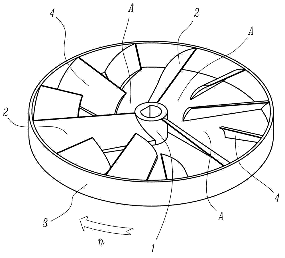
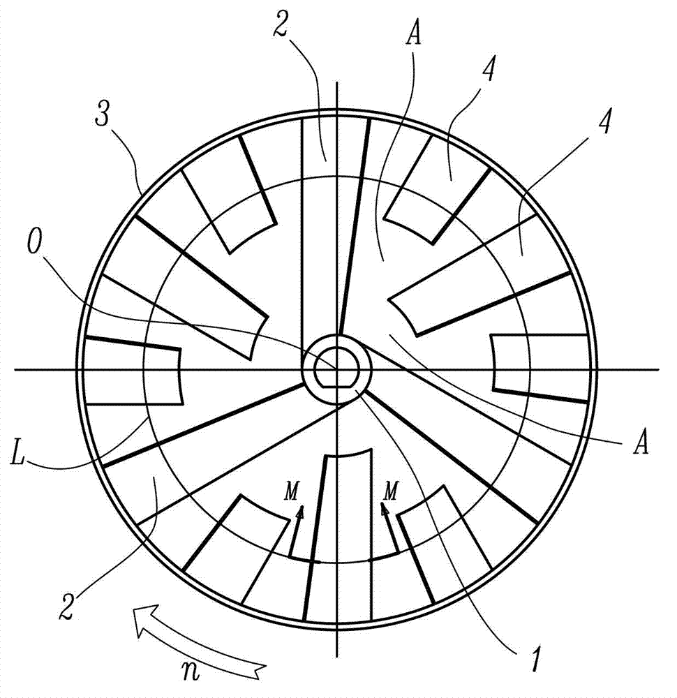
[0022] An axial fluid drive device, which includes a hub 1, fan blades 2 and a fairing 3, wherein the fan blades 2 are radially arranged between the hub 1 and the fairing 3, and the hub 1, the fan blades 2 and the fairing 3 Rotate together synchronously, the fan blade 2 is a strip-shaped blade with a certain width, and the fan blade 2 and its rotation plane present a certain inclination angle to generate an axial driving force for the fluid working medium; the characteristics of the present invention are: There are suspended blades 4, the inner end of the suspended blades 4 adopts a cantilever structure, and the outer end of the suspended blades 4 is tightly connected with the fairing 3 or made in one structure with the fairing 3; the fairing 3 can be a closed-loop structure (such as figure 1 and figure 2 shown) can also be an open-loop structure (not shown in the figur...


PUM


Abstract

The invention belongs to the field of fluid machines and relates to an axial flow type fluid driving device. The axial flow type fluid driving device comprises a hub, fan blades and a fairing which rotate together, wherein the fan blades are of radial fan blade structures and are arranged between the hub and the fairing. The axial flow type fluid driving device is characterized in that suspension blades are arranged on the axial flow type fluid driving device; the inner end of the suspension blades are of a cantilever structure; and the outer end of the suspension blades are in fastening connection with the fairing or are integrally formed with the fairing. Due to the adoption of the suspension blade structure, at least part of fan blades and the hub are not connected to yield part of axial inlet channel area, further the passing flow of a working medium can be increased and the conveying efficiency of the device is increased. The weight and the rotary inertia are reduced, so that the possibility of fatigue damage of a driving shaft of the device is reduced; the lengths of the blades are inconsistent, so that the action rules of the blades for the working medium or the action rules of the working medium for the blades are inconsistent, the noises can be reduced by suppressing the resonance phenomenon and the work reliability of the device is improved.

Description

technical field [0001] The invention belongs to the technical field of fluid machinery, and relates to a fluid drive device, in particular to an axial flow fluid drive device, and more specifically to a vane structure and layout of an axial flow fan and an axial flow vane pump . Background technique [0002] Axial-flow fluid drive devices include axial-flow fans and axial-flow vane pumps, etc., which belong to typical fluid machinery. The function of the axial-flow fluid drive device is to drive the fluid working medium through the rotation of the fan blades, so as to generate a flow mainly along the axial direction of the drive shaft. The working medium conveyed by the axial flow fan is generally a gaseous fluid, while the working medium conveyed by the axial flow vane pump is generally a liquid fluid. Whether it is an axial flow fan or an axial flow vane pump, the working fluid they transport is not only a single type of substance and a single fluid state, but also often...

Claims


Application Information

Patent Timeline
Patent Type & Authority Applications(China)
IPC IPC(8): F04D29/18F04D3/00F04D29/32F04D29/38F04D19/00F04D29/00
Inventor 阮勤江耿爱农陈君立
Owner ZHEJIANG HONGYOU AIR COMPRESSOR MFG
Learn More