
High-heat-dissipation-rate foil type axial thrust bearing, combined bearing and heat management method

A high-speed foil type and thrust bearing technology, applied in the direction of shafts and bearings, bearings, bearing components, etc., can solve the problem of reducing the maximum load capacity of foil type aerodynamics, the incomplete formation of air film 405, and the small amount of cooling air, etc. problem, to achieve enhanced convective cooling heat transfer effect, enhanced cooling heat transfer effect, and increased cooling gas flow

Active Publication Date: 2021-06-22
北京伯肯当代氢燃料电池实验室有限公司 +1
View PDF17 Cites 0 Cited by
  • Summary
  • Abstract
  • Description
  • Claims
  • Application Information

AI Technical Summary

Problems solved by technology

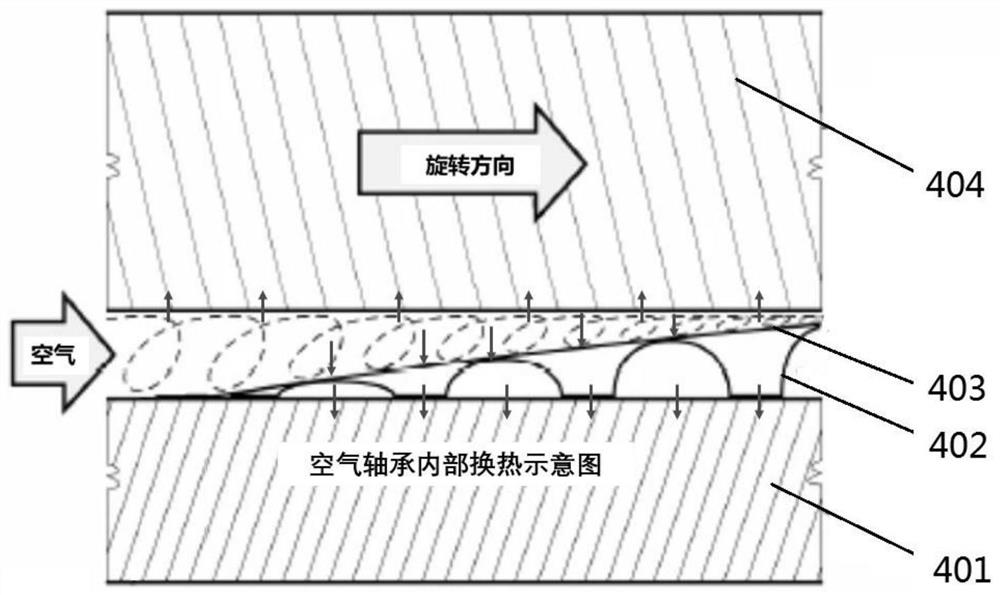
[0005] (1) It will cause overheating of the material of the corrugated elastic foil 402: the corrugated elastic foil 402 is usually made of nickel-based superalloy Inconel. As the temperature increases, its elastic modulus will decrease, resulting in a softening effect. This softening effect increases the compliance of the foil aerodynamic bearing, thereby reducing the maximum load capacity of the foil aerodynamic bearing; moreover, studies have shown that the stiffness (and possibly damping) characteristics of the foil aerodynamic bearing also will change as a result, which will greatly affect the rotordynamic performance of the system
[0006] (2) It will seriously affect the performance of the top smooth foil 403 coating; in order to reduce the cost of fuel cell air compressors, the foil-type aerodynamic bearings generally use a low-temperature coating with a simple process, and the working temperature of the low-temperature coating is generally It is required to be below 200°C, too high temperature will reduce the performance of the coating, or even fall off
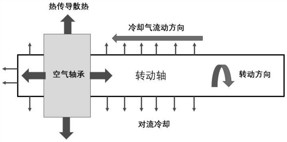
[0007] (3) Foil-type aerodynamic bearings may also produce self-sustaining cycles (that is, thermal runaway), which may lead to serious failures; since the shaft 404 absorbs most of the heat during the operation of the bearing, the expansion speed of the shaft is faster than that of the bearing. Thereby increasing the preload of the bearing, as the bearing preload continues to increase, just like the additional radial load between the shaft 4 and the bearing continues to increase, this will amplify the stress on the fluid film and cause additional Heat generation and further expansion of the shaft, resulting in the appearance of self-sustaining cycles (ie, thermal runaway)
[0008] (4) In the axial direction, the temperature cannot be transmitted in time, and an excessively high axial thermal gradient will be formed from the inside of the foil aerodynamic bearing to the axial edge, and the excessive axial thermal gradient will cause the top smooth foil to produce Distortion, which in turn interferes with the formation of the air film 405 or prevents the formation of the air film 405 completely, which can cause bearing failure at high speeds and / or high load levels
Although some people use forced airflow to pass through the bearing gap to achieve bearing cooling, but because the gap gap is small, the channel flow resistance is large, and the amount of cooling air is too small, the effect is not very obvious

Method used


Image

  • High-heat-dissipation-rate foil type axial thrust bearing, combined bearing and heat management method
  • High-heat-dissipation-rate foil type axial thrust bearing, combined bearing and heat management method
  • High-heat-dissipation-rate foil type axial thrust bearing, combined bearing and heat management method

Examples


Embodiment 1

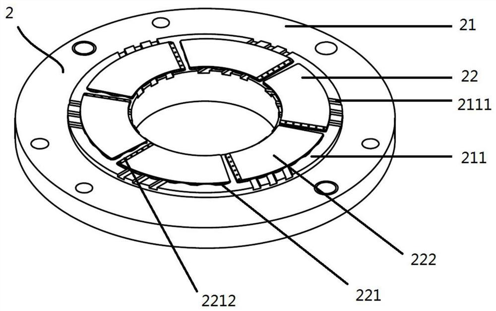
[0053] Such as Figure 3-8 As shown, a foil-type axial thrust bearing 2 with high heat dissipation rate includes a base body 21 and six fan-shaped annular foil groups 22. The end face of the base body 21 is coaxially provided with an annular boss 211, and the six said The fan ring foil groups 22 are arranged on the end surface of the ring boss 211 symmetrically and non-overlappingly to the center of the circumference; and there are radial gaps between the side edges of adjacent fan ring foil groups. Each of the fan-shaped ring-shaped foil sets 22 includes a smooth foil 222 and a corrugated elastic foil 221, and the corrugated elastic foil 221 and the smooth foil 222 are both fan-shaped and stacked in sequence and welded to the ring. The upper surface of the boss 211, that is, the corrugated elastic foil 221 is interposed between the boss 211 and the smooth foil 222; and corresponds to the corrugated upper convex portion 2211 of the corrugated elastic foil 221, The upper surfa...

Embodiment 2

[0058] A high heat dissipation rate foil type composite bearing 3, such as Figure 9-13 As shown, it includes a high heat dissipation rate foil type radial bearing 4 and the above-mentioned high heat dissipation rate foil type axial thrust bearing 2, and the non-working end surface of the high heat dissipation rate foil type axial thrust bearing 2 (without One side of the fan ring foil group 22 is fixed) and the end surface of the bearing shell 41 side of the high heat dissipation rate foil radial bearing 4 is coaxially connected, or the high heat dissipation rate foil type axial thrust The non-working end face side of the bearing 2 extends outward in the axial direction to form a bearing shell 41 of the foil radial bearing 4 .

[0059] As a preference, the inner surface of the high heat dissipation foil radial bearing 4 is coaxial and is provided with an axial corrugated elastic foil 42 and an axial smooth foil 43 sequentially along its radial direction, and the axial smooth ...

Embodiment 3

[0065]In the fuel cell air compressor, micro gas turbine, or oil-free fan, the above-mentioned high heat dissipation rate foil type axial thrust bearing 4 and high heat dissipation rate foil type combined bearing 3 are assembled to the rotor 5 and the motor casing Between body 1, the application in air compressors for fuel cells such as Figure 14 As shown, the end of the rotor 5 close to the impeller 7 and the volute 8 is provided with a thrust plate 51 .

[0066] On the right side of the thrust plate 51 (the side where the impeller 7 and the volute 8 are located) assemble a described high heat dissipation rate foil type axial thrust bearing 2, and assemble the high heat dissipation on the left side of the thrust plate 51 Foil type combined bearing 3 with high heat dissipation rate, and the working end faces of the high heat dissipation rate foil type axial thrust bearing and the high heat dissipation rate foil type combined bearing 3 are arranged facing the thrust plate 51 ....


PUM


Abstract

According to the high-heat-dissipation-rate foil type axial thrust bearing, combined bearing and bearing heat management method, a plane boss is additionally arranged in the center of a base, end face cooling air grooves are additionally formed on the boss, and the number and the positions of the cooling air grooves correspond to the corrugation design and the corrugation positions of the corrugated elastic foils; on one hand, the boss provides support for the corrugated elastic foil, facilitates machining of the end face cooling air grooves and provides convenience for radial cooling of the thrust bearing, and on the other hand, the boss increases a gap between the thrust bearing and the surface of the combined bearing base, and more choices are provided for design of cooling flow channels of a whole bearing system. On one hand, the end face cooling air grooves expand the area of a cooling air flow channel, reduce flow resistance and increase the flow of the cooling air, so that the cooling heat transfer effect on the smooth foil and the corrugated elastic foil is enhanced, and the temperature of the thrust bearing is reduced.

Description

technical field [0001] The invention relates to the technical field of thermal management of air foil bearings, in particular to a high heat dissipation rate foil axial thrust bearing, a combined bearing and a thermal management method. Background technique [0002] A fuel cell is a device that directly converts the chemical energy of hydrogen and oxygen into electrical energy through an electrode reaction. Among them, the products after the chemical reaction of hydrogen and oxygen are mainly water and heat. Therefore, fuel cells are considered to be the main source of future automobile power because of their clean properties. At present, the research and application of fuel cells for automobile power mainly focus on proton exchange membrane fuel cells (PEMFC). In the core technology of the fuel cell, the electric stack can be compared to the "heart" of the fuel cell, which is the core of generating electric energy, and the air compressor can be called the "lung" of the fu...

Claims


Application Information

Patent Timeline
IPC IPC(8): F16C17/04F16C17/26F16C37/00
CPCF16C17/042F16C17/26F16C37/00F16C2380/26
Inventor 肖育民徐子介徐焕宇
Owner 北京伯肯当代氢燃料电池实验室有限公司
Learn More