
Laser displacement measuring method based on digital speckle correlation method (DSCM)

A technology of digital speckle correlation and laser displacement, applied in the direction of measuring devices, optical devices, instruments, etc., can solve the problems of poor effect and roughness, and achieve the effect of convenient operation, accurate measurement and good real-time performance

Inactive Publication Date: 2013-03-13
HUAZHONG UNIV OF SCI & TECH
View PDF4 Cites 12 Cited by
  • Summary
  • Abstract
  • Description
  • Claims
  • Application Information

AI Technical Summary

Problems solved by technology

However, the surface of the object is rough, and when strong scattering occurs, the scattered light spots received by the CCD will be submerged in the speckle noise. At this time, the technical measures to suppress the speckle effect will be very ineffective

Method used


Image

  • Laser displacement measuring method based on digital speckle correlation method (DSCM)
  • Laser displacement measuring method based on digital speckle correlation method (DSCM)
  • Laser displacement measuring method based on digital speckle correlation method (DSCM)

Examples


Embodiment

[0048]The laser uses a power-adjustable laser (model DI650-1-3) as the light source, and its output power is 1mw, so the adjustment range of the laser power is 0-1mw. The optical signal receiver used is TCD1501D linear array CCD, its maximum driving frequency is 6MHZ, and the minimum driving frequency is 1MHZ. When the counter value of the driving chip counts to 4570, a full signal is generated, and the sampling period (1 / driving frequency) is multiplied by The counter value is the light integration time, so the light integration time of the circuit is 0.77ms-4.57ms. When the signal received by the CCD is too weak, signal amplification is required. In the circuit design, a 20kΩ digital potentiometer is used to adjust the magnification. The pre-resistance is 1kΩ, so the adjustment range of the CCD amplification gain is 1-20 times.

[0049] The imaging lens is the model GCL-304 (focal length F=20mm) produced by Daheng Optoelectronics. According to the magnification, the object d...


PUM


Abstract

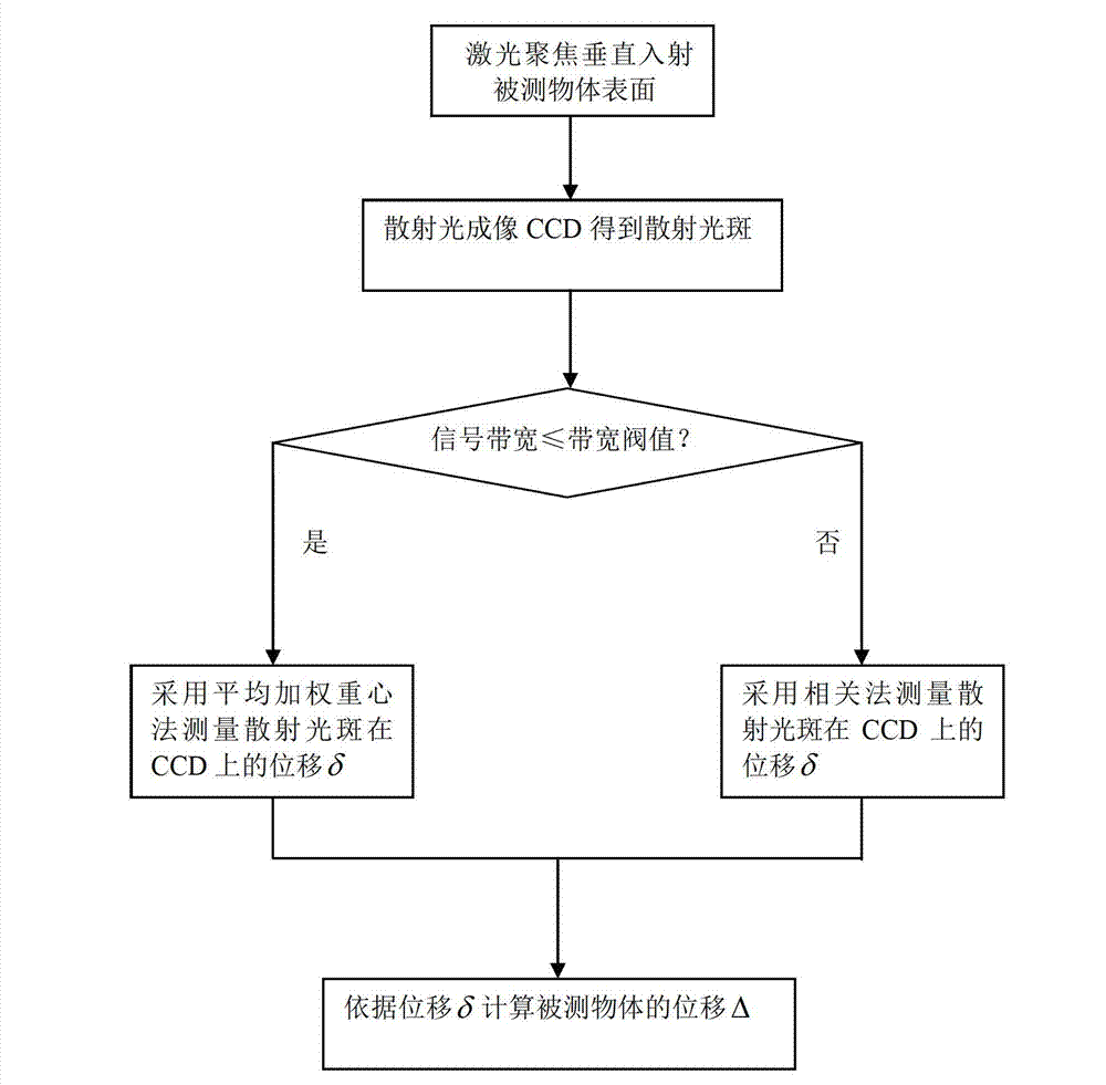
The invention discloses a laser displacement measuring method based on a DSCM. The method includes that lasers are vertically shot into a moving measured object surface through focusing; scattered light at incident spots on the measured object surface is received and is imaged on the sensitive surface of a charge coupled device (CCD) through an imaging lens to obtain scattering spots; when the signal bandwidth of the scattering spots is smaller than or equal to a bandwidth threshold, the measured object surface is indicated to be a weak scattering interface, and displacements of the scattering spots on the CCD are measured by using an average weighted centroid method; when the signal bandwidth of the scattering spots is larger than the bandwidth threshold, the measured object surface is indicated to be a strong scattering interface, and displacements of the scattering spots on the CCD are measured by using a correlation method; and the displacement of the measured object is calculated according to the displacements of the scattering spots on the CCD. According to the method, accurate measurement of displacements of various roughness object surfaces is achieved, and the measurement is rapid and accurate.

Description

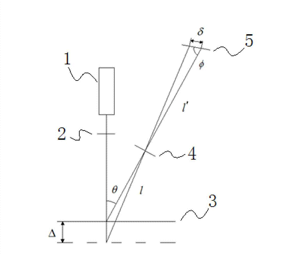
technical field [0001] The invention relates to the field of displacement sensing measurement, in particular to a laser displacement measurement method based on a digital speckle correlation method, which is suitable for strong scattering and rough interface displacement measurement. Background technique [0002] Laser triangulation displacement sensor is an important sensor for non-contact displacement measurement, widely used in three-dimensional profile, thickness, width, material level, and vibration measurement. It uses the diffuse reflection spot formed by projecting the laser beam onto the measured object surface as a sensing signal, and uses the lens imaging principle to converge the collected diffuse reflection light to the light receiver on the focal plane to form an image point. The receiver can be a spot position detector (CCD) or a position sensitive device PSD. When using the theory of laser triangulation to measure the displacement of the surface of the objec...

Claims


Application Information

Patent Timeline
Patent Type & Authority Applications(China)
IPC IPC(8): G01B11/02
Inventor 李顶根沈磊朱鸿茂褚俊罗锋刘明勇
Owner HUAZHONG UNIV OF SCI & TECH
Learn More