Winding process of electronic current mutual inductor based on Rogowski coil

A current transformer, electronic technology, applied in the direction of coil manufacturing, etc., can solve problems such as difficult cross-section of wire turns, insufficient loop manufacturing process, excessive positioning gap, etc., to eliminate the influence of coil output accuracy and facilitate batch production Create and optimize the effect of electromagnetic parameters

Inactive Publication Date: 2013-03-13
CHINA TIANSHUI CHANGCHENG SWITCHGEAR CO LTD
View PDF4 Cites 5 Cited by
  • Summary
  • Abstract
  • Description
  • Claims
  • Application Information

AI Technical Summary

Problems solved by technology

[0003] Winding on a traditional winding machine, there are problems such as the coil skeleton is easily deformed when the coil skeleton is positioned, the winding is easy to break, and the positioning gap of each link of the winding machine system is too large, so it is difficult to wind high-precision Rogowski coils tightly and evenly.
In the traditional manual winding process, there are problems such as the tight and uniform winding of the turns is difficult to control, the cross section of the turns is not easy to be perpendicular to the coil skeleton, and the loop manufacturing process is not sophisticated enough. Ultimately, the inherent output accuracy of the coil cannot be well guaranteed. More inconvenient for mass production

Method used


Image

  • Winding process of electronic current mutual inductor based on Rogowski coil
  • Winding process of electronic current mutual inductor based on Rogowski coil
  • Winding process of electronic current mutual inductor based on Rogowski coil

Examples


Embodiment Construction

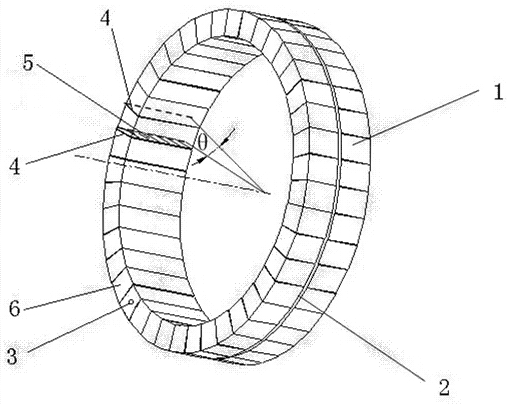
[0017] Such as figure 1 As shown, an electronic current transformer coil based on a Rogowski coil, the size of the coil bobbin 1 is as follows: the inner diameter is 160mm, the outer diameter is 180mm, the thickness of the coil bobbin 1 is 9.8mm, and the outer surface of the coil bobbin 1 has a loop groove 2; the winding diameter is 0.45mm. Coil winding steps are as follows:

[0018] (1) Use a 66-hole indexing disc to evenly draw the partition line 4 on the outer surface of the circular coil skeleton 1, and draw the line every 8 holes, and the central angle between adjacent partition lines 4 is θ=( 9 / 66)*8=1.09°, a total of 330 partition lines are drawn; the partition line 4 is an annular closed line formed around the cross section of the coil bobbin 1, and the closed section 5 formed by the annular partition line is in line with the circumference of the coil bobbin 1 The lines are perpendicular.

[0019] (2) On the outer surface 6 of the coil bobbin 1, open a process hole ...


PUM


Abstract

The invention provides a winding process of an electronic current mutual inductor based on a Rogowski coil, which comprises the steps of: (1) depicting an identifying break line uniformly on the outer surface of a circular coil framework, wherein the break line is vertical to the circumference of the circular coil framework, and distances between adjacent break lines are equal; and (2) winding a loop first along a loop groove of the coil framework; and then, maintaining a constant hand power with the break line as reference, winding a coil uniformly on the coil framework so that the turns of the coils between adjacent break lines is equal in number. According to the winding process of the electronic current mutual inductor based on the Rogowski coil provided by the invention, the coil is winded with the break line as reference, and the verticality of the wire turn section relative to the coil framework is ensured in low cost, and the wire turn is distributed compactly and uniformly, so that the electromagnetic parameters of the coil are optimized, and the consistency of the wire turn of the coil is ensured, and uniformity of the output voltage of the coil is ensured. The winding process of the electronic current mutual inductor based on the Rogowski coil provided by the invention facilitates batch production.

Description

technical field [0001] The invention belongs to the technical field of electrical equipment, and relates to a coil winding process of an electronic current transformer based on a Rogowski coil. Background technique [0002] With the construction of my country's smart grid and the development of technology, the application of electronic current transformers in smart substations has been initially promoted, mainly used to complete the precise measurement and protection of the primary conductor current. In the field of medium voltage level, the coils of electronic current transformers are mainly Rogowski coils (air core coils) and low power iron core coils. Electronic current transformers based on Rogowski coils have attracted attention because of their good linearity, wide frequency bandwidth, and non-saturation. There are many factors that affect the accuracy of the Rogowski coil, among which the uniformity and tightness of the coil winding and the verticality of the plane o...

Claims


Application Information

Patent Timeline
IPC IPC(8): H01F41/06H01F41/08
Inventor 李菊红于庆瑞赵刚
Owner CHINA TIANSHUI CHANGCHENG SWITCHGEAR CO LTD
Why Eureka
Try Eureka