Starting method of modular multi-level flexible direct-current transmission converter

A flexible DC power transmission, modular multi-level technology, applied in output power conversion devices, electrical components, etc., can solve the problem of intensifying the internal dependence of valve control system hardware, high control system resource consumption, and poor operability, etc. problems, to achieve the effect of simplifying the starting method, reducing requirements, and ensuring consistency

Active Publication Date: 2013-03-13
XJ ELECTRIC +1
4 Cites 29 Cited by

AI-Extracted Technical Summary

Problems solved by technology

[0010] Among the charging methods of the above two sub-modules, the first charging method is to charge each sub-module one by one, the charging time is long, and if the sub-module control circuit takes power from both ends of the DC capacitor of the sub-module, it will cause the sub-module that completes charging first The voltage will complete the discharge process within a certain period of time. For the actual system, this method is not very operable; one of the defects of the second charging method is that it does not consider the difference in circuit parameters of the sub-module itself and the difference in the DC power load of the sub-module. For the sub-module The influence of natural charging uneven voltage; the second defect is that the voltage equalization strategy...

Abstract

The invention relates to a starting method of a modular multi-level flexible direct-current transmission converter. The method comprises the following steps: realizing switch between soft start and a normal operating circuit through on-off of a circuit breaker and a line contactor; in the soft start process, cutting off the highest direct current voltage of a sub module at a certain frequency to ensure even charge of a bridge arm sub module; and ensuring that the voltage of the bridge arm sub module reaches a system operational rated value by selecting the cutting number of the sub modules so as to create condition for the system for smooth switch from the soft start process to the control mode. A single bridge arm in the control stage is used as a unit control unit, and even charge control of the sub module is carried out for each bridge arm at the same time. Thus, charging is easier to realize without detecting the current of the bridge arm. The soft start process is remarkably shortened, and the even charging degree of the sub modules is very high.

Application Domain

Technology Topic

Image

  • Starting method of modular multi-level flexible direct-current transmission converter
  • Starting method of modular multi-level flexible direct-current transmission converter
  • Starting method of modular multi-level flexible direct-current transmission converter

Examples

  • Experimental program(1)

Example Embodiment

[0025] The specific embodiments of the present invention will be further introduced below.
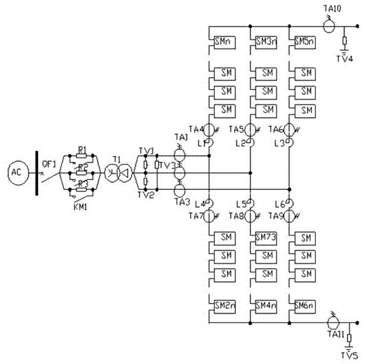
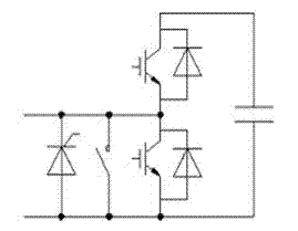
[0026] The basic topology of the modular multilevel flexible DC transmission converter is as follows figure 1 shown, figure 2 It is a schematic diagram of the sub-module structure. The modular multi-level flexible DC transmission converter consists of six three-phase bridges, each phase bridge consists of two bridge arms, and each bridge arm is cascaded by a bridge arm reactor and several sub-modules. made. The number of submodules contained in a single bridge arm is represented by Nsm. The sub-module is the basic unit of the converter. The topology of the sub-module is as follows: figure 2 As shown in the figure, it includes a DC capacitor, an upper-tube IGBT connected in series with the DC capacitor, and a lower-tube IGBT connected in parallel with the DC capacitor. There are diodes in the upper and lower IGBT tubes in anti-phase and parallel with them, and the sub-module also includes a protective side The circuit switch and thyristor are connected to both ends of the lower IGBT.
[0027] When the sub-module is connected to the bridge arm of the converter, the upper tube is disconnected and the lower tube is closed, since the lower tube is connected in parallel with the capacitor, the capacitor is short-circuited through the lower tube at this time, and the capacitor is cut off. No matter how, it will not form a loop with the capacitor of the sub-module, and will not perform charging and discharging operations on the sub-module. When the sub-module is connected to the bridge arm of the converter, and the upper and lower tubes are both disconnected, if the bridge arm current is in the charging direction, the current will pass through the anti-parallel diode of the upper tube IGBT to charge the sub-module capacitor; When the arm current is in the discharge direction, it cannot flow in this switching state.
[0028] image 3 The flow chart of the start-up method of the modular multi-level flexible DC transmission converter is given, and the specific method is as follows:
[0029] (1) Select the number of sub-modules Nsm_d to be removed during the soft-start process of the system. The selection of this parameter makes the voltage of each sub-module after precharging close to the rated operating voltage of the system (set the number of bridge arm sub-modules in the system) is Nsm);
[0030] (2) Close the AC side circuit breaker QF1, and the grid voltage AC will precharge the sub-modules on the six bridge arms through the soft-start resistor;
[0031](3) Start the voltage equalization control strategy in the soft start stage immediately after closing the AC circuit breaker (the uniform control strategy here refers to the following steps 4-6);
[0032] (4) Take one bridge arm as the unit control unit to sort the voltages of the sub-modules inside each bridge arm. The sorting procedure of sub-modules can directly adopt the sub-module sorting procedure under normal operation mode;
[0033] (5) For the Nsm_d sub-modules with higher internal voltage of each bridge arm, the operation of closing the lower tube of the sub-module is issued, and for the remaining (Nsm-Nsm_d) sub-modules, the operation of blocking the pulses of the upper tube and the lower tube is adopted, that is, disconnecting The operation of the upper and lower pipes;
[0034] (6) Repeat steps (4) and (5) at the set frequency until the sub-module voltage is in a stable state (if the control frequency is too low, it will not be able to achieve the purpose of sub-module capacitor voltage equalization, and it needs to be large enough, but Can not be too high to affect the system switching loss);
[0035] (7) When the system detects that the voltage of each sub-module is in a stable state, closes the soft-start resistance bypass contactor KM1, the soft-start process is completed, and the software system can switch to the normal control mode for control.
[0036] In the above steps 4, 5, and 6, the higher-voltage sub-module is removed during the soft-start charging process of the sub-module, and the upper tube of the lower-voltage sub-module is in the pulse blocking stage. The low-voltage sub-module performs the charging operation.
[0037] In step (1), Nsm_d is selected according to the charging steady-state voltage. For example, the DC voltage is 1000V, and the bridge arm has 13 sub-modules. If each sub-module needs to be charged to 100V, 3 sub-modules need to be removed so that the remaining 10 sub-modules are just responsible for the charge. 1000V voltage. Nsm represents the total number of sub-modules of a single bridge arm, the number of sub-modules of each bridge arm is the same, and the number of removed sub-modules of each bridge arm is the same.
[0038] The frequency set in step (6) is not strictly limited. If it is too low, the sub-module voltage equalization may be affected. If it is too high, it is unnecessary. Generally, it is recommended to be 500Hz.
[0039] Figure 4 , 5 It is the capacitor voltage waveform of the four sub-modules on the first bridge arm of a modular multi-level flexible DC transmission converter. It can be seen from the figure that the four sub-modules with different characteristics are under the soft-start method described in this paper. The voltages of the sub-modules are kept the same to a large extent, achieving the effect of voltage equalization and synchronous soft-start.
[0040] The above enumeration is only a number of specific embodiments of the present invention, the present invention is not limited to the above embodiments, and there can be many modifications, and all modifications that those of ordinary skill in the art can directly derive or associate from the content disclosed in the present invention, All should be considered as the protection scope of the present invention.

PUM

no PUM

Description & Claims & Application Information

We can also present the details of the Description, Claims and Application information to help users get a comprehensive understanding of the technical details of the patent, such as background art, summary of invention, brief description of drawings, description of embodiments, and other original content. On the other hand, users can also determine the specific scope of protection of the technology through the list of claims; as well as understand the changes in the life cycle of the technology with the presentation of the patent timeline. Login to view more.

Similar technology patents

General wiper connecting apparatus

Owner:DANYANG UPC AUTO PARTS

Preparation method of silicon dioxide aerogel

InactiveCN104961135ALow costLower requirementSilicon compoundsSupercritical dryingIndustrial waste
Owner:ZHUO DA NEW MATERIAL TECH GRP

Classification and recommendation of technical efficacy words

Why Eureka
Try Eureka