Permanent magnet synchronous motor control method

A permanent magnet synchronous motor and control method technology, applied in the direction of motor generator control, electronic commutation motor control, control system, etc., can solve the problem of system chattering affecting the observation accuracy, increasing the complexity of system design, and difficult to achieve improvement effects, etc. problems, to achieve the effect of eliminating chattering, reducing chattering problems, and strong robustness

Inactive Publication Date: 2013-03-13
XIAN UNIV OF TECH
View PDF2 Cites 38 Cited by
  • Summary
  • Abstract
  • Description
  • Claims
  • Application Information

AI Technical Summary

Problems solved by technology

The observer is used to observe the load disturbance and compensate it. This method can reduce the chattering by reducing the nonlinear term, but the complexity of the system design is increased due to the increase of the observer, and the system chattering has an influence Observation accuracy, it is difficult to achieve the ideal improvement effect in practice

Method used


Image

  • Permanent magnet synchronous motor control method
  • Permanent magnet synchronous motor control method
  • Permanent magnet synchronous motor control method

Examples


Embodiment Construction

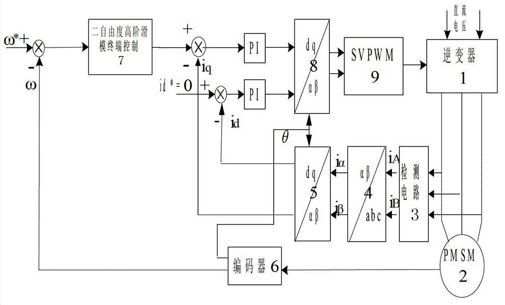
[0014] A permanent magnet synchronous motor control method, using a vector control system, the vector control system includes two parts, a speed outer loop and a current inner loop, mainly including a main circuit, a current signal detection circuit 3 and a control circuit; see figure 1 , the main circuit includes the inverter 1 and the PMSM module 2, the current signal detection circuit 3 detects the three-phase current of the motor in the three-phase stationary coordinate system through the Hall sensor, and takes the two-phase output current i A ,i B , after Clarke transformation 4, converted to the current value i in the stationary two-phase coordinate system α ,i β , in the speed loop, the given speed w * Compared with the feedback speed w measured by the encoder 6, after being adjusted by the two-degree-of-freedom high-order sliding mode non-singular terminal control outer loop controller 7, the q-axis current i in the rotor rotating coordinate system is output q * ,,...


PUM


Abstract

The invention discloses a permanent magnet synchronous motor control method in which a vector control system is used. The vector control system comprises an outer speed ring and an inner current ring, and a PI (proportional-integral) controller of a rotating speed ring is replaced with a two-DOF (degree of freedom) higher-order nonsingular terminal sliding mode controller; the input of the two-DOF higher-order nonsingular terminal sliding mode controller is the difference between the given rotating speed w* of a motor and the actual feedback rotating speed w* of the motor; the error between the given rotating speed and the feedback rotating speed is judged, when the error of the rotating speed is less than Xi, an output exciting current iq* is calculated by a simple higher-order nonsingular terminal sliding mode controller; when the error of the rotating speed is greater than Xi, the output of the two-DOF higher-order nonsingular terminal sliding mode controller is an output iq* controlled by a higher-order nonsingular terminal sliding mode and the sum of the output and compensation gain of the higher-order nonsingular terminal sliding mode; and the size of Xi can be set according to actual situations and needs. According to the method, the system control accuracy is improved and the rapid convergence of the rotating speed of the motor is realized; and the method has strong robustness on load disturbances.

Description

technical field [0001] The invention relates to a control method of a permanent magnet synchronous motor. Background technique [0002] Permanent Magnet Synchronous Motor (Permanent Magnet Synchronous Motor abbreviated as PMSM) has the advantages of low inertia, fast response, high power density, low loss, and high efficiency. And with the substantial improvement of the performance of permanent magnet materials, its application in the field of industrial production automation will become more and more extensive. However, since the permanent magnet synchronous motor is a high-order, nonlinear, strongly coupled multivariable system, and there are uncertainties such as parameter perturbation and load disturbance, it is difficult to control it with high performance. At present, many control methods for PMSM have been proposed, such as adaptive control, fuzzy control, neural network, active disturbance rejection control and so on. But these are rarely used in actual engineering...

Claims


Application Information

Patent Timeline
Patent Type & Authority Applications(China)
IPC IPC(8): H02P21/00H02P21/14H02P21/05H02P21/16
Inventor 尹忠刚李东钟彦儒
Owner XIAN UNIV OF TECH
Why Eureka
Try Eureka