Sound receiving system

A sound receiving system and microphone technology, applied in the field of sound processing, can solve the problems of howling, poor angle, and long distance of the sound reinforcement system, and achieve good sound reinforcement effect and simple structure

Active Publication Date: 2013-03-13
GUANGZHOU RUIFENG AUDIO TECH
View PDF2 Cites 12 Cited by
  • Summary
  • Abstract
  • Description
  • Claims
  • Application Information

AI Technical Summary

Problems solved by technology

[0002] In the application of sound reinforcement equipment, the main problem affecting the gain of sound reinforcement is: the direct sound received by the microphone and the signal of the sound wave fed back due to various reasons are of the same frequency and phase, so it is easy to make the sound reinforcement system Produce positive feedback and cause howling
In situations where the sound environment is relatively complex, it is often difficult to obtain a better sound pickup (sound transmission) effect
For example, the distance between the target sound source and the sound pickup (sound transmission) device is long, the angle is not good, the background noise is large, or the feedback is strong, which may lead to the reduction of output gain, distortion or howling.
In particular, when the sound reinforcement equipment needs the support of many sound pickup (sound transmission) equipment, the complexity of its regulation and debugging can be imagined

Method used


Image

  • Sound receiving system
  • Sound receiving system
  • Sound receiving system

Examples


Embodiment Construction

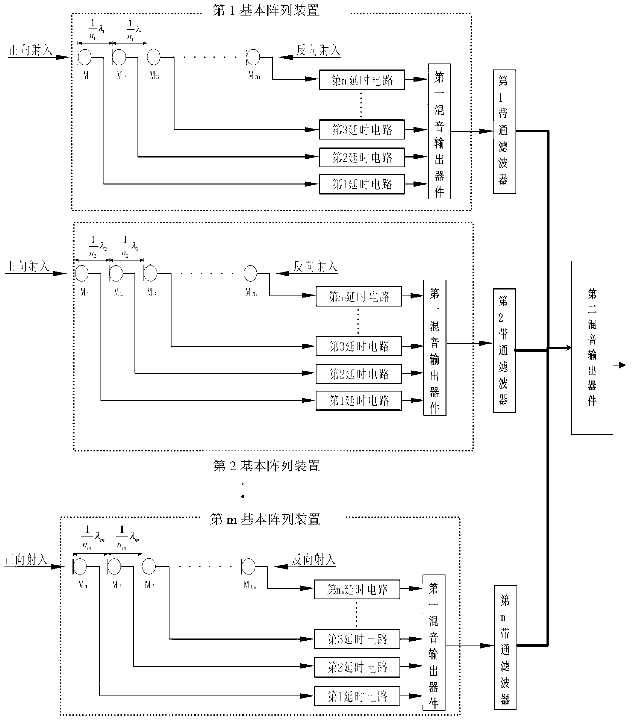
[0030] Depend on figure 1 As shown, a sound receiving system includes a plurality of basic array devices, a plurality of filters and a second mixing output device, the output terminals of the plurality of basic array devices are respectively connected to a filter, and the output of the plurality of filters Both ends are connected to the input end of the second mixing output device, and the output end of the second mixing output device is the output end of the local sound receiving system. The plurality of filters described can all be set as band-pass filters.

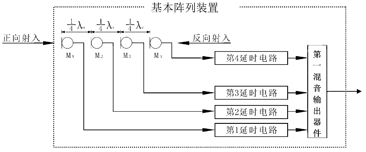
[0031] The basic array device includes a microphone array, a delay circuit and a first mixing output device, and the microphone array includes a plurality of microphones M 1 , M 2 , M 3 ... M n , and the frequency response, sensitivity, and directivity characteristics of each microphone are basically the same.

[0032] The plurality of microphones M 1 , M 2 , M 3 ... M n Arranged vertically along a straight lin...


PUM


Abstract

The invention discloses a sound receiving system. Output ends of a plurality of basic array devices are connected with filters respectively, output ends of a plurality of filters are connected with an input end of a second sound mixing output device, each of the basic array devices comprises a microphone array which comprises a plurality of microphones, the plurality of microphones are longitudinally arranged sequentially along a straight line, the spacing distance between two adjacent microphones is as follows, an output end of each of the microphones is connected with a time-delay circuit respectively, output ends of a plurality of time-delay circuits are connected with an input end of a first sound mixing output device, and the delay time of the i time-delay circuit is the sum of the delay time of the last time-delay circuit and (n-i) times of the unit time. By the aid of the sound receiving system, within the set frequency bandwidth, the output gain which can improve positive acoustic wave excitation can be achieved, the output gain of non-positive acoustic waves can be greatly restrained, and required directivity characteristics can be obtained. The sound receiving system is widely used in the pickup (sound transmission) field.

Description

technical field [0001] The invention relates to sound processing technology, in particular to a sound receiving system comprising a longitudinal linear array composed of a plurality of microphones. Background technique [0002] In the application of sound reinforcement equipment, the main problem affecting the gain of sound reinforcement is: the direct sound received by the microphone and the signal of the sound wave fed back due to various reasons are of the same frequency and phase, so it is easy to make the sound reinforcement system Positive feedback is generated to cause howling. [0003] The feedback sound wave and the sound wave that the microphone should accept are generally not in the same direction. The most common solution is to enhance the directional characteristics of the microphone and reduce the influence of the feedback sound wave. [0004] The existing cardioid and supercardioid directional microphones are generally the most sensitive to the sound waves in...

Claims


Application Information

Patent Timeline
Patent Type & Authority Applications(China)
IPC IPC(8): H04R3/02H04R27/00
CPCH04R1/406H04R3/005H04R2201/403H04R1/08
Inventor 胡秉奇陈建业梁勇
Owner GUANGZHOU RUIFENG AUDIO TECH
Why Eureka
Try Eureka