
Method for recalibrating coordinate positioning apparatus

A coordinate positioning and recalibration technology, applied in the direction of measuring devices, instruments, electrical digital data processing, etc., can solve problems such as inaccuracy, time-consuming measurement, and destructive production process of coordinate positioning equipment

Inactive Publication Date: 2013-03-13
RENISHAW PLC
View PDF9 Cites 35 Cited by
  • Summary
  • Abstract
  • Description
  • Claims
  • Application Information

AI Technical Summary

Problems solved by technology

Although methods are known to reduce the time required to perform an overall calibration, for example by deriving some calibration data from other calibration data, these methods are still relatively time consuming and may introduce an unacceptable level of measurement imprecision in certain situations
In some cases, the calibration process may thus last many minutes or even many hours, and taking the coordinate positioning device offline to perform the calibration may be disruptive to the production process

Method used


Image

  • Method for recalibrating coordinate positioning apparatus
  • Method for recalibrating coordinate positioning apparatus
  • Method for recalibrating coordinate positioning apparatus

Examples


Embodiment Construction

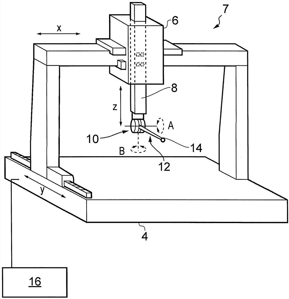
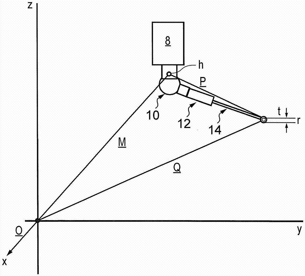
[0044] refer to figure 1 , shows a coordinate positioning device in the form of a coordinate measuring machine (CMM)2. The CMM 2 includes a base or table 4 on which an object, such as a workpiece, can be placed, and a stage 6 movable relative to the base 4 in x and y directions. The gantry 6 comprises a spindle 8 which is movable relative to the gantry 6 in the z-direction. Position encoders are provided on each axis of the CMM2 to measure the position of the spindle in x, y and z directions. The measurement of the spindle position is therefore carried out in the so-called machine coordinate (x, y, z) system.

[0045] The spindle 8 supports an indexing probe head 10, such as the PH10 motorized probe head from Renishaw. The indexing probe head 10 includes a base attachment that attaches to the spindle 8 and a probe attachment that supports a scanning probe 12 having a deflectable stylus 14 . Scanning probe 12, which may include a Renishaw SP25 probe, includes an internal se...


PUM


Abstract

A method is described for recalibrating coordinate positioning apparatus (2) after a disturbance, such as a stylus replacement. The coordinate positioning apparatus comprises a platform (8), a measurement probe (12) and a probe head (10) for reorienting the measurement probe (12) relative to the platform (8). A calibration data set is taken for the coordinate positioning apparatus (2) that comprises datum data for a plurality of orientations of the measurement probe. The datum data includes at least first datum data for a first nominal orientation of the measurement probe. After a disturbance to the coordinate positioning apparatus (2), the calibration data set is updated by acquiring one or more position measurements and calculating a first correction from the one or more position measurements. The first correction describes any change in the first datum data following the disturbance and is used to update the datum data for a plurality of different orientations of the measurement probe (12). Corresponding apparatus is also described.

Description

technical field [0001] The present invention relates to a coordinate positioning device and in particular to a method for rapidly recalibrating a coordinate measuring machine (CMM) comprising a probe head and a measuring probe. Background technique [0002] Various types of coordinate positioning apparatus are known, such as coordinate measuring machines, machine tools, industrial robots, and the like. Coordinate positioning devices typically include sensors that measure the position of a movable platform or spindle in a so-called machine (eg X, Y, Z) coordinate system. A measurement probe is attached to and moved by a movable platform or spindle with which the position of a point on the surface of the object is measured. It is also often desirable to mount the measurement probe to the platform of the coordinate positioning machine by means of a probe head which allows the orientation of the measurement probe to be adjusted relative to the main axis. In particular, the abi...

Claims


Application Information

Patent Timeline
Patent Type & Authority Applications(China)
IPC IPC(8): G01B21/04
CPCG06F15/00G01B21/042
Inventor 利奥·克里斯托弗·萨默维尔
Owner RENISHAW PLC
Learn More