Half-thread spongy bone hollow screw

A technology of hollow screw and loose thread, applied in the direction of internal bone synthesis, fixer, fastening device, etc., can solve the problem that hollow screw cannot meet the clinical needs, achieve good holding force and stability, easy to use, and simple structure Effect

Inactive Publication Date: 2013-03-20
唐佩福 +2
View PDF5 Cites 4 Cited by
  • Summary
  • Abstract
  • Description
  • Claims
  • Application Information

AI Technical Summary

Problems solved by technology

Currently in clinical practice, commonly used hollow screws are difficult to meet clinical needs

Method used


Image

  • Half-thread spongy bone hollow screw
  • Half-thread spongy bone hollow screw

Examples


Embodiment Construction

[0009] In order to understand the technical solution of the present invention in more detail, the present invention will be specifically described below in conjunction with the accompanying drawings.

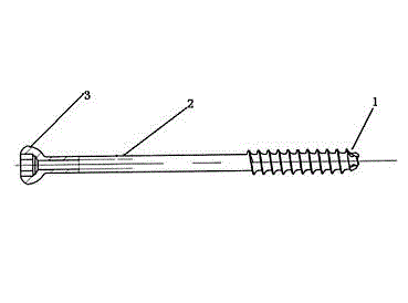
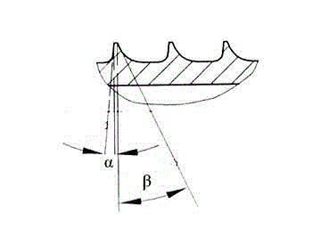
[0010] Such as figure 1 , 2 As shown, the half-thread cancellous bone hollow screw of the present invention includes a nail head 1, a nail shaft 2 and a nail tail 3, and the length of the half-thread cancellous bone hollow screw is 35-140mm. The nail shank 2 is a hollow titanium alloy shank with a through hole with a diameter of 2.2 mm inside. The nail shank 2 includes a threaded section with a length of 32 mm at the front end and a non-threaded section at the tail end. The diameter of the non-threaded section is 3.6 mm. The major thread diameter of the thread segment is 5.5mm, the minor thread diameter is 3.5mm, the pitch is 1.75mm, the thread thickness is 0.1mm, and the working angle α of the tooth profile is 5 0 , tooth profile non-working angle β is 25 0 , The chamfering ...


PUM


Abstract

The invention relates to a half-thread spongy bone hollow screw which comprises a nail head (1), a nail rod (2) and a nail tail (3). The hollow screw has a total length of 35 to 140mm; the nail rod (2) is a titanium alloy nail body; a through hole with a diameter of 2.2mm is formed in the nail rod (2); and the nail rod (2) comprises a threaded section at the front end and an unthreaded section at the tail end. The half-thread spongy bone hollow screw disclosed by the invention has a simple structure and is simple and convenient to use.

Description

technical field [0001] The invention relates to an orthopedic medical device, in particular to a half-thread cancellous bone hollow screw. Background technique [0002] With the economic construction and the development of the automobile industry, the incidence of high-energy injuries is increasing day by day. For patients with high-energy pelvic ring injuries, the injuries are often serious and complicated, and treatment is very difficult for both doctors and patients. In the past 20 years, with the development of anatomy and imaging technology, the minimally invasive percutaneous hollow screw fixation technique has the advantages of less trauma, less blood loss, less soft tissue damage, lower postoperative infection rate, faster postoperative recovery and ectopic fixation. The low incidence of ossification has been widely used in various fields of minimally invasive orthopedics. However, due to different anatomical fractures and injuries, the requirements for cannulated ...

Claims


Application Information

Patent Timeline
Patent Type & Authority Applications(China)
IPC IPC(8): A61B17/86
Inventor 唐佩福张立海司庆华张英泽
Owner 唐佩福
Why Eureka
Try Eureka