Mechanical vibration device of continuous casting machine

A technology of mechanical vibration and vibration device, applied in the field of vibration device, can solve the problems of high maintenance cost and high purchase cost, and achieve the effects of low maintenance cost, uniform vibration and low purchase cost

Active Publication Date: 2015-05-20
宁波中超机器有限公司
View PDF6 Cites 0 Cited by
  • Summary
  • Abstract
  • Description
  • Claims
  • Application Information

AI Technical Summary

Problems solved by technology

Since hydraulic vibration needs to be controlled by PLC and expensive vibration servo valves need to be purchased, the purchase cost of the device is high, and the maintenance cost is also high

Method used


Image

  • Mechanical vibration device of continuous casting machine
  • Mechanical vibration device of continuous casting machine
  • Mechanical vibration device of continuous casting machine

Examples


Embodiment Construction

[0021] The following are specific embodiments of the present invention and in conjunction with the accompanying drawings, the technical solutions of the present invention are further described, but the present invention is not limited to these embodiments.

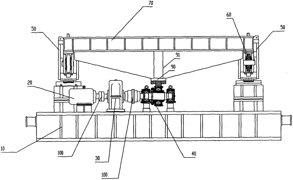
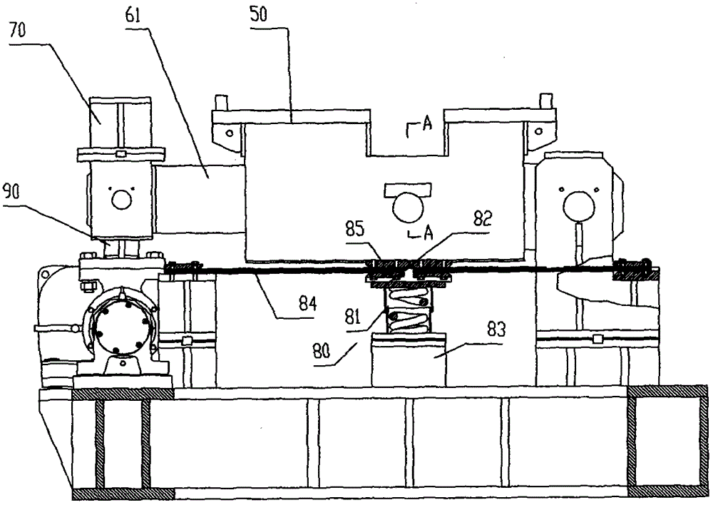
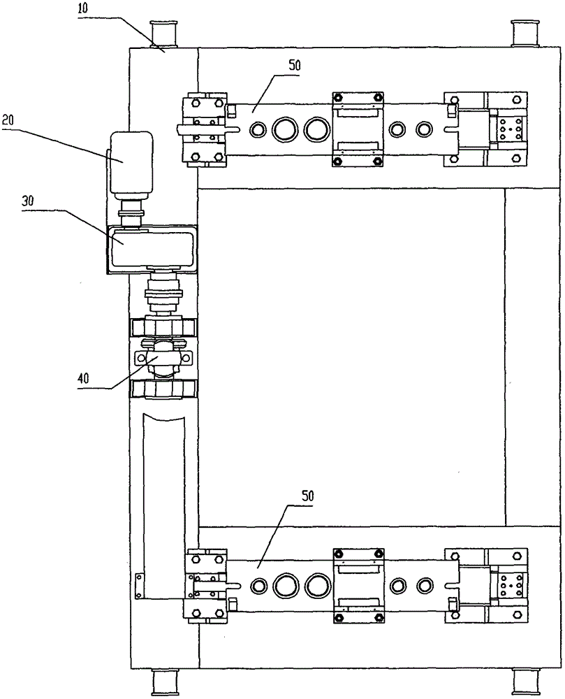
[0022] Please refer to figure 1 , figure 2 , image 3 The continuous casting machine mechanical vibration device of the present invention comprises a vibration device base 10, a motor 20 fixedly arranged on the vibration device base 10, a vibration reducer 30 and an eccentric wheel device 40, and the motor 20, the vibration reducer 30 and the eccentric wheel device 40 The bottom surface of the inverted trapezoidal push rod 90 is fixedly connected to the casing of the eccentric wheel device 40, and the two ends of the top surface are respectively fixedly connected to the connecting rod device 60 used to support the vibrating table frame 50. The left and right sides The vibrating table 50 is fixedly connected by a grid-sh...


PUM


Abstract

The invention provides a mechanical vibration device of a continuous casting machine, which belongs to the field of machinery, and is used for solving the problem of high control cost of the existing mechanical vibration device. The mechanical vibration device comprises a vibration device base, a motor, a vibration speed reducer, an eccentric wheel device, a push rod, a synchronous connecting rod, a connecting rod device and an elastic supporting device. The mechanical vibration device utilizes a motor to drive an eccentric wheel to vibrate, the vibration rack is vibrated through the vibration of the eccentric wheel, and the mechanical vibration device has the beneficial effects of low purchasement cost and maintenance cost; and in addition, the mechanical vibration device utilizes the devices of the synchronous connecting rod, the inverse trapezoid push rod, a connecting plate and the like to keep the vibration amplitudes of the vibration rack on the left side and the right side consistent, so that the vibration is more uniform.

Description

technical field [0001] The invention relates to the field of vibrating devices, in particular to a mechanical vibrating device for a continuous casting machine. Background technique [0002] The development direction of modern continuous casting technology is fast pouring technology, which leads to the optimal design of the vibration mode in the continuous casting process of billets. In the continuous casting process, the purpose of vibration is to prevent the casting from sticking to the surface of the crystallizer installed on the vibration device, and at the same time obtain a good casting surface. [0003] Existing continuous casting machines usually adopt hydraulic vibration mode. The power unit of hydraulic vibration is a hydraulic power station, which serves as a power source to provide oil with stable pressure and flow to the vibrating hydraulic cylinder. The signal of the hydraulic power station is controlled by the computer in the main station room through the PL...

Claims


Application Information

Patent Timeline
Patent Type & Authority Patents(China)
IPC IPC(8): B22D11/053
Inventor 徐功立
Owner 宁波中超机器有限公司
Why Eureka
Try Eureka