Multifunction wing tip turbine engine having fore-lying impellers

A turbine, multi-purpose technology, applied in the field of wingtip turbines, which can solve the problems of increasing the weight and complexity of the aircraft, not eliminating the wingtip vortex, and difficult to judge the speed range.

Inactive Publication Date: 2013-03-20
刘婉婷 +2
View PDF5 Cites 8 Cited by
  • Summary
  • Abstract
  • Description
  • Claims
  • Application Information

AI Technical Summary

Problems solved by technology

[0004] 1. Winglets are used, which do not reduce the threat to the safety of the rear aircraft from the wingtip wake vortex drawn by the forward aircraft, and are mostly used for drag reduction of long-range large passenger aircraft models, because this method increases the weight and complexity of the aircraft , the drag reduction effect is not large, so the general aircraft is less used, such as Airbus aircraft designers occasionally use this design, but American Boeing rarely uses this design;
[0005] 2. The use of wingtip modification, such as cutting the wingtips and using elliptical wingtips as much as possible, can reduce drag slightly, but it does not eliminate the wingtip vortex and its resistance, nor does it reduce the wingtips dragged out by the forward aircraft The safety threat of the wake vortex to the following aircraft;
[0006] 3. Using wingtip sails, the drag reduction effect of this method is better than that of winglets, but the design is extremely difficult, and the suitable speed range is difficult to judge;
[0007] 4. The impeller is placed in the middle of the wingtip (that is, between the leading edge and the trailing edge of the wing) or the turbine at the rear of the wingtip. The turbine blades are passively driven by the vortex turned up by the wingtip, and the rotation direction of the blade is the same as that on the wingtip. The turning vortex is the same, thus generating electricity, but it does not eliminate the wingtip vortex that has been generated in front of it, so its drag-reducing and lift-increasing effect needs to be improved;

Method used


Image

  • Multifunction wing tip turbine engine having fore-lying impellers
  • Multifunction wing tip turbine engine having fore-lying impellers
  • Multifunction wing tip turbine engine having fore-lying impellers

Examples


Embodiment Construction

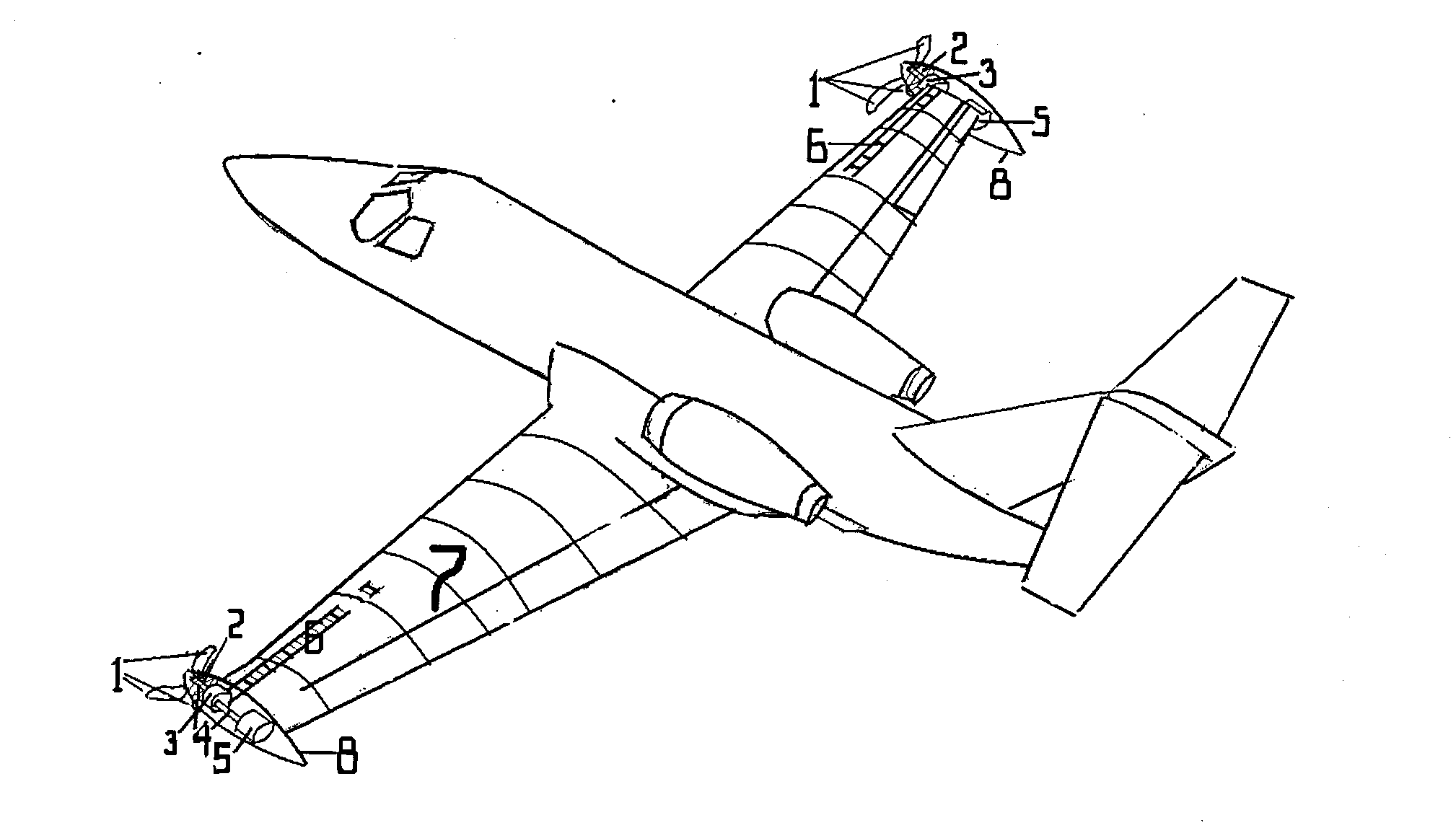
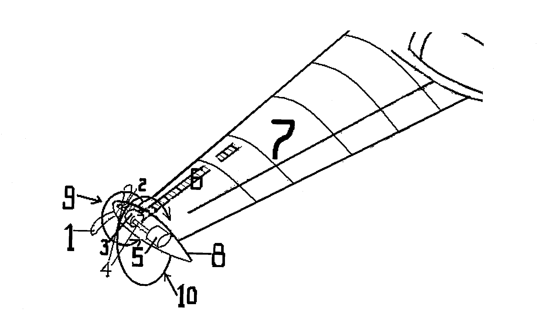
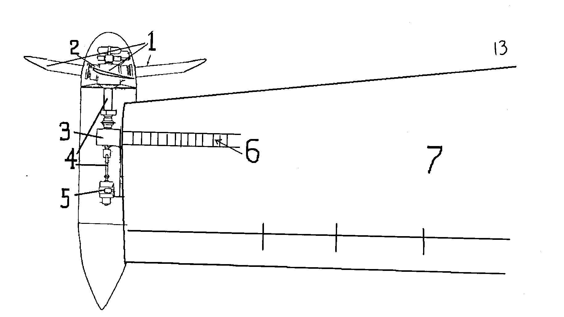
[0018] The invention is a brand-new wing auxiliary device or a new type of wing, which installs one or more turns of impellers at the front of the wingtips, the impellers are composed of blades and impeller shafts, and there are fairings on the front and rear of the impeller shaft discs. Extending to the entire wingtip, the blades are in the shape of propellers or fan blades, and are installed in front of the wingtips through hubs, gears and rotating shafts to drive power generation or other transmission equipment installed at the wingtips. The diameter of the impeller should not be too large, and the specific size should be determined by the specific model and specific speed range. To put it in detail, the present invention is most suitable for use on aircraft with a cruising speed of 300 to 1050 kilometers, such as China's Yun-7, Yun-8, MA600, ARJ21, C919, foreign "King Air", Boeing 737 Such as medium-sized transport aircraft, passenger aircraft, medium-sized early warning a...


PUM


Abstract

The invention relates to completely-new wing auxiliary equipment or a novel wing. According to the present invention, the front part of a wing tip is provided with a circle or a plurality of circles of impellers, a fairing is arranged on the front and the rear of a shaft disc of the impeller and extends to the whole wing tip, variable pitch blades are arranged in front of the wing tip through a wheel hub, a gear and a rotation shaft, and drive an electricity generation device arranged on the wing tip position or other transmission devices, the impeller is driven to rotate through facing airflow, the blade can rotate in a direction against an upward turning eddy flow of the wing tip under pushing of the incoming flow with an installation angle ( as shown in Figure 1) of the blade, such that right wing tip counterclockwise rotation wing tip eddy flow generated in the normal wing profile is previously decreased, rotation airflows generated by the impellers on both edges upward impact the wings from the bottom of the wings so as to further increase lifting force, and substantial lifting increase and resistance reduction are achieved with the benign effects. The multifunction wing tip turbine engine even can replace an electromotor driven by the aircraft motor part or generate auxiliary power, such that safety threat on the back flying aircraft by the wing tip wake of the front flying aircraft can be decreased, and aviation industry safety can be improved.

Description

Technical field [0001] The present invention relates to a kind of wingtip turbine that the impeller is installed in the front of the wingtip (or called "wingtip", hereinafter collectively referred to as "wingtip") to reduce the wingtip vortex and its induced resistance in a specific direction of rotation. Increase the lift and generate continuous electric energy or auxiliary power, and can also greatly reduce the threat to the safety of the rear aircraft caused by the wingtip wake vortex dragged by the forward aircraft. It can also be said that this invention is a new type of wing, which belongs to the aviation industry. technology. Background technique [0002] On the one hand, many current aircraft, especially transport aircraft, passenger aircraft, early warning aircraft, trainer aircraft, attack aircraft, aerial refueling aircraft, anti-submarine aircraft, electronic reconnaissance aircraft, etc., require a lot of electricity during flight, and most of their power comes ...

Claims


Application Information

Patent Timeline
Patent Type & Authority Applications(China)
IPC IPC(8): B64C23/00F03D9/00F03D1/06
CPCY02E10/725Y02E10/721Y02E10/72
Inventor 江闻杰
Owner 刘婉婷
Why Eureka
Try Eureka