Method for relieving vibratory stress of loader front frame

A technology of vibration aging and front frame is applied in the field of vibration aging treatment of the front frame of a loader, which can solve problems such as high noise, and achieve the effects of reducing operation time, fewer failures, and improving work efficiency.

Inactive Publication Date: 2013-03-20
NANNING SHENHUA VSR TECH RES INST
View PDF2 Cites 4 Cited by
  • Summary
  • Abstract
  • Description
  • Claims
  • Application Information

AI Technical Summary

Problems solved by technology

[0003] The technical problem to be solved by the present invention is to provide a quick and effective method for eliminating the residual stress of the front frame of the loader in the vibration aging process of the front frame of the loader. The problem

Method used


Image

  • Method for relieving vibratory stress of loader front frame
  • Method for relieving vibratory stress of loader front frame
  • Method for relieving vibratory stress of loader front frame

Examples


Embodiment 1

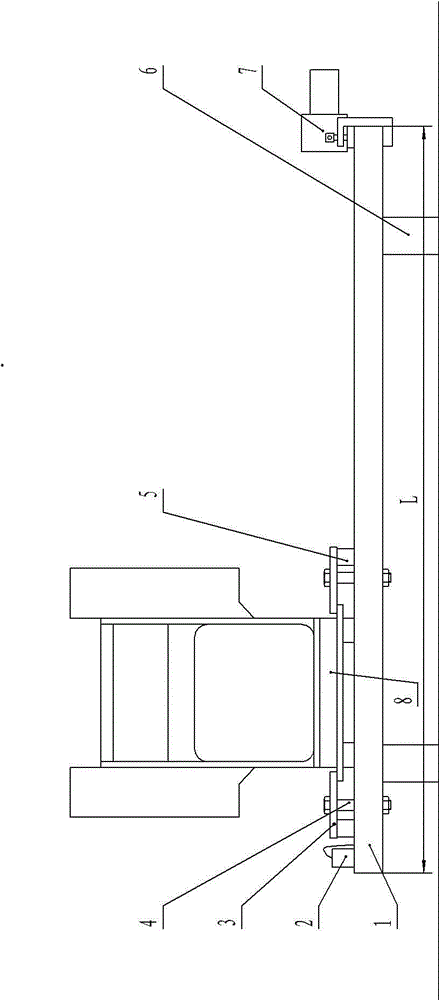
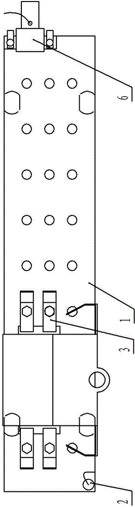
[0019] The front frame of the loader is a box-shaped structural part welded by multiple steel plates, and there are base bosses on both sides of the front frame of the loader; figure 1 and figure 2 The shown loader front frame vibration aging device, this loader front frame vibration aging device includes a vibration exciter 7 and a vibration measuring device 2, there is a platform 1, the length of the platform 1 is 4000 mm, and the width is 800 mm mm, a steel plate with a thickness of 100 mm; there are three rows distributed on the table top of platform 1, and each row has nine uniformly distributed holes with a diameter of 38 mm; each through-hole end at the bottom of the table top of platform 1 is welded with a screw The nut that the hole is communicated with the through hole, the nut of the present embodiment is M36; Four pressing plates 3 and four spacers 5 are placed on the platform 1 table of the present embodiment, and the pressing plates 3 are respectively worn in th...

Embodiment 2

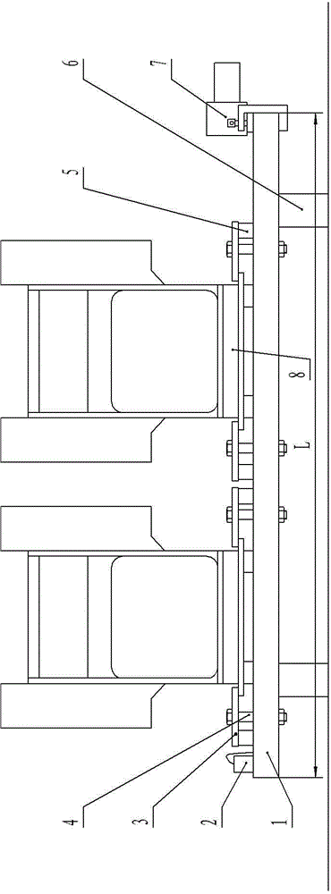
[0023] The front frame of the loader is a box-shaped structural part welded by multiple steel plates, and there are base bosses on both sides of the front frame of the loader; image 3 and Figure 4 The shown loader front frame vibration aging device, this loader front frame vibration aging device includes a vibration exciter 7 and a vibration measuring device 2, there is a platform 1, the length of the platform 1 is 4000 mm, and the width is 800 mm mm, a steel plate with a thickness of 100 mm; there are three rows distributed on the table top of platform 1, and each row has nine uniformly distributed holes with a diameter of 38 mm; each through-hole end at the bottom of the table top of platform 1 is welded with a screw The nut that the hole communicates with the through hole, the nut of the present embodiment is M36; Eight pressing plates 3 and eight pads 5 are placed on the platform 1 table top of the present embodiment, and the pressing plates 3 are respectively worn in th...


PUM

PropertyMeasurementUnit
Lengthaaaaaaaaaa
Widthaaaaaaaaaa
Thicknessaaaaaaaaaa

Abstract

The invention discloses a method for relieving vibratory stress of a loader front frame and relates to the technical field of stress relief of metal components, wherein a vibratory stress relief device for the loader front frame is used. The method comprises the operation steps of horizontally placing the platform top of the vibratory stress relief device for the loader front frame; placing a rubber pad between a platform and the ground, wherein the outer edge of the rubber pad is close to two side edges of the platform and the distance between the center of the rubber pad and a platform top end is 2 / 9*L mm; fixing the loader front frame on the platform top; and starting a vibration exciter for vibrating for 15-30min under the vibratory stress relief frequency. Compared with the prior art, the method has the advantages of fast and effectively eliminating the welding residual stress of the loader front frame and solving the problem of high noise in the existing vibratory stress relief treatment of the loader front frame.

Description

technical field [0001] The invention relates to the technical field of stress relief treatment of metal components, in particular to a method for performing vibration aging treatment on the front frame of a loader. Background technique [0002] The front frame of the loader is the main force-bearing member when the loader is operating, and it is the core component of the entire working device. The front frame of the loader is a box-shaped structural part made of steel plates welded, with many welding parts and a complex structure; in the damage investigation and statistics of the front frame of the loader, the damage to the welds of the front frame is relatively Many, the reason is mainly due to the welding residual stress produced by the front frame of the loader after welding; the residual stress has a great influence on the dimensional accuracy, stability and bearing capacity of the front frame of the loader, and it is necessary to eliminate its residual stress stress. ...

Claims


Application Information

Patent Timeline
IPC IPC(8): C21D10/00
Inventor 杨胜锋熊文府杨坤杨秀山樊雄农群武杨胜钦张绍明曾念波陈运寿黄海李艳
Owner NANNING SHENHUA VSR TECH RES INST
Why Eureka
Try Eureka