
Involute tooth-thickness variable non-circular gear transmission

A technology for non-circular gears and variable tooth thickness, which is applied in gear transmissions, transmissions, belts/chains/gears, etc., and can solve problems such as manufacturing errors, complex process parameters, and small coincidence

Inactive Publication Date: 2013-03-20
CHONGQING UNIV
View PDF3 Cites 6 Cited by
  • Summary
  • Abstract
  • Description
  • Claims
  • Application Information

AI Technical Summary

Problems solved by technology

Although these gear transmissions have the advantages of large transmission ratio and high load-carrying capacity, and show good meshing performance in the case of transmission with large shaft angles (close to 90°), but for small shaft angles (less than 45°) transmission conditions And under high-speed transmission conditions, worm gear transmission, face gear transmission, spiral bevel gear transmission and hypoid gear transmission have the disadvantages of small coincidence, high noise, and sensitivity to manufacturing errors and assembly errors in the actual transmission process. In addition, the above gears all need special machine tool processing, and the adjustment of process parameters is extremely complicated.

Method used


Image

  • Involute tooth-thickness variable non-circular gear transmission
  • Involute tooth-thickness variable non-circular gear transmission
  • Involute tooth-thickness variable non-circular gear transmission

Examples


no. 1 example

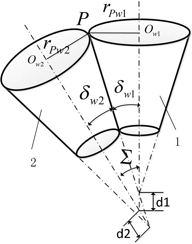
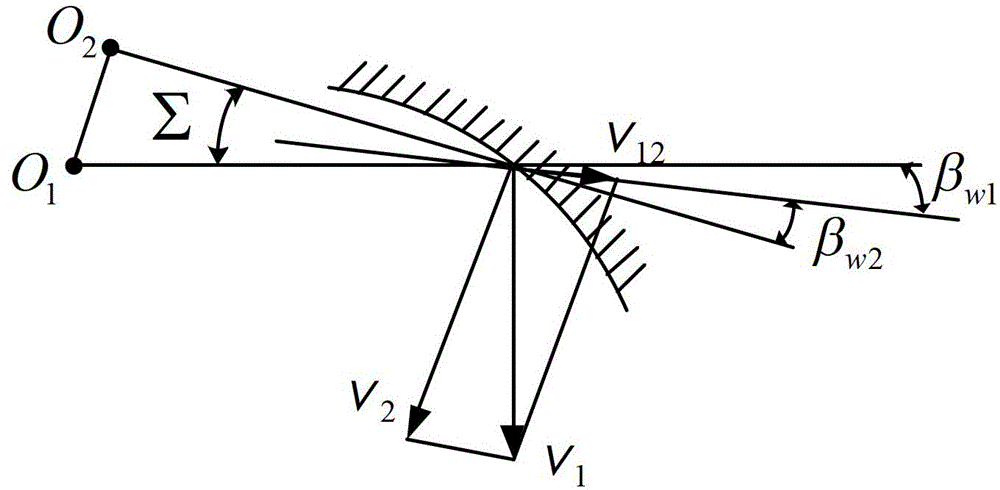
[0046] like figure 1 As shown, it is a schematic view of the conical surface of the working section of the first embodiment of the involute variable tooth thickness non-circular gear transmission of the present invention. The involute variable-tooth-thickness non-circular gear transmission of this embodiment includes an involute variable-tooth-thickness non-circular gear I1 and an involute variable-tooth-thickness non-circular gear II2 that mesh with each other, and the involute variable-tooth-thickness non-circular gear The axis of I1 and the axis of the involute variable tooth thickness non-circular gear II2 are parallel to or intersect with the plane, and:

[0047] ∑=δ w1 +δ w2

[0048] beta w1 =-β w2 ;

[0049] Among them, δ w1 is the working pitch cone angle of the involute variable tooth thickness non-circular gear I;

[0050] δ w2 is the working pitch cone angle of the involute variable tooth thickness non-circular gear II;

[0051] beta w1 is the helix angle...

no. 2 example

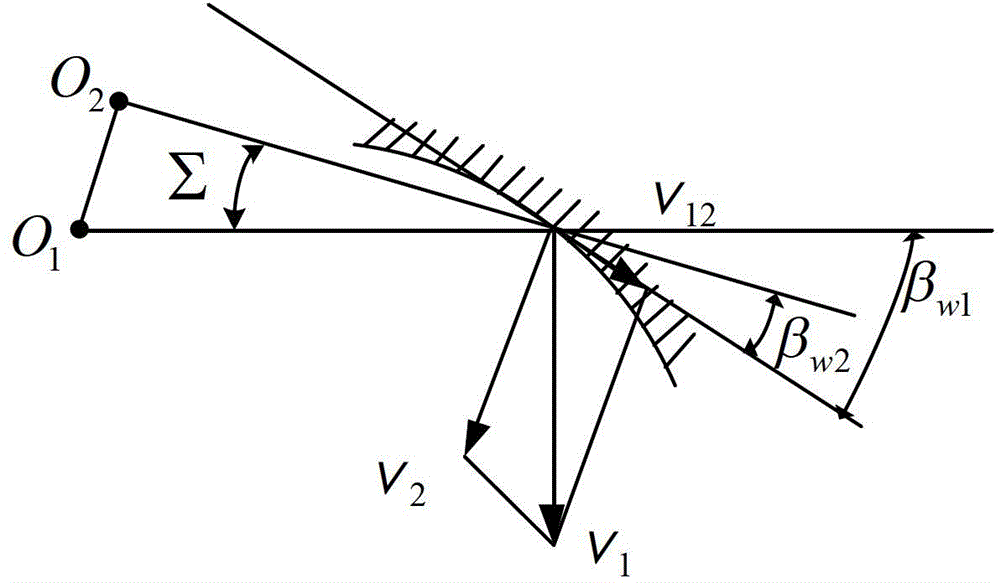
[0067] like Figure 4 As shown, it is a schematic view of the conical surface of the working section of the second embodiment of the involute variable tooth thickness non-circular gear transmission of the present invention. The involute variable-tooth-thickness non-circular gear transmission in this embodiment includes an involute variable-tooth-thickness non-circular gear I1 and an involute variable-tooth-thickness non-circular gear II2 that mesh with each other. The axis of the involute variable-tooth-thickness non-circular gear I1 and the axis of the involute variable-tooth-thickness non-circular gear II2 of the present embodiment are staggered in space, and:

[0068] cos ( β w 1 + β w 2 ) = tan δ w ...


PUM


Abstract

The invention discloses involute tooth-thickness variable non-circular gear transmission. The device comprises an involute tooth-thickness variable non-circular gear I and an involute tooth-thickness variable non-circular gear II, which are meshed with each other, wherein the axes of the involute tooth-thickness variable non-circular gear I and the involute tooth-thickness variable non-circular gear II are parallel in a plane or intersected in the plane, or the axes of the involute tooth-thickness variable non-circular gear I and the involute tooth-thickness variable non-circular gear II are spatially crossed. As the axes of the involute tooth-thickness variable non-circular gear I and the involute tooth-thickness variable non-circular gear II are parallel or intersected in the plane or spatially crossed, the involute tooth-thickness variable non-circular gear transmission can be utilized to realize spatial transmission, which not only inherits the advantages of high strength, good rigidity, convenience for manufacturing and processing and high reliability of involute tooth-thickness variable gear transmission of spatial parallel axes, concurrent axes and alternating axes, but also meets the requirement of gear ratio transmission.

Description

technical field [0001] The invention relates to a gear transmission, in particular to an involute variable tooth thickness non-circular gear transmission. Background technique [0002] At present, the main ways to realize spatial inclination gear transmission are worm gear transmission, face gear transmission, spiral bevel gear transmission and hypoid gear transmission. Although these gear transmissions have the advantages of large transmission ratio, high bearing capacity, and show good meshing performance under the transmission condition of large shaft angle (close to 90°), but for the transmission condition of small shaft angle (less than 45°) Under the condition of high-speed transmission, worm gear transmission, face gear transmission, spiral bevel gear transmission and hypoid gear transmission have the disadvantages of small coincidence, high noise, and sensitivity to manufacturing errors and assembly errors in the actual transmission process. Moreover, the above gear...

Claims


Application Information

Patent Timeline
IPC IPC(8): F16H1/12F16H1/14
Inventor 朱才朝刘立斌杜雪松刘明勇
Owner CHONGQING UNIV
Learn More