Passivation illuminating system with damage detection and implementation method thereof

A damage detection and lighting system technology, applied in the field of lighting systems, can solve problems such as lightning introduction and failure to completely solve lighting problems in high-risk places, and achieve the effect of easy maintenance

Active Publication Date: 2013-03-20
GUANGDONG INST OF INTELLIGENT MFG
View PDF4 Cites 2 Cited by
  • Summary
  • Abstract
  • Description
  • Claims
  • Application Information

AI Technical Summary

Problems solved by technology

Since it is necessary to introduce devices such as wires into the lighting area, this will lead to the introduction of lightning, so the problem of intrinsically safe lighting in high-risk places has not been completely solved.

Method used


Image

  • Passivation illuminating system with damage detection and implementation method thereof
  • Passivation illuminating system with damage detection and implementation method thereof

Examples


Embodiment Construction

[0023] In order to make the purpose, technical solutions and advantages of the present invention clearer, the implementation of the present invention will be further described in detail below in conjunction with the accompanying drawings:

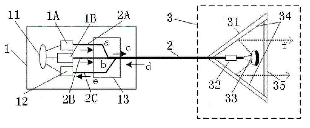
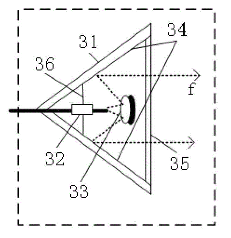
[0024] This embodiment provides a passive lighting system with damage detection. The system includes: a main control unit 1 emitting invisible light, an optical fiber 2 and a passive lamp 3. lamp connection; the main control unit includes a controller 11, a laser, an optical fiber, a photodetector 12 and an optical coupler 13; Powder 33; the

[0025] A controller for controlling the emission of the laser and receiving information from the photodetector;

[0026] Optical fiber for long-distance energy transmission;

[0027] An optical coupler is used to fuse light of different wavelengths emitted by different lasers into the same optical fiber; and

[0028] Return light from one of the lasers reflected by the grating to the photodetector;...


PUM

PropertyMeasurementUnit
Center wavelengthaaaaaaaaaa

Abstract

The invention discloses a passivation illuminating system with damage detection and an implementation method thereof. The system comprises a main control unit, an optical fiber and a passivation lamp, wherein the main control unit is used for emitting invisible lights; the main control unit is connected with the passivation lamp through the optical fiber and comprises a controller, a laser, an optical fiber, an optical detector and an optical coupler; the passivation lamp comprises a shell, an optical fiber, an optical grating and a photoluminescence powder; the optical fiber is arranged in the shell; the controller is used for controlling the laser to transmit and receive information of the optical detector; the optical fiber is used for realizing remote energy transmission; the optical coupler is used for fusing lights with different wavelengths, which are emitted by different lasers, to the same optical fiber and returning lights of one laser reflected by the optical grating to the optical detector; the optical detector is used for receiving lights returned by the optical fiber through the optical coupler; and the photoluminescence powder is used for receiving lights emitted by the optical grating and up-converting and down-converting the lights into visible lights.

Description

technical field [0001] The invention relates to a lighting system used in high-risk places, in particular to a passive lighting system with damage detection and a realization method. Background technique [0002] With the rapid development of my country's economy and the strengthening of national defense forces, the safety management of high-risk places is becoming more and more important. The use of passive lighting in flammable and explosive environments in high-risk places will become one of the important facilities for our army's rear caverns, munitions production, and coal mine safety management. With the introduction of automation and information equipment in high-risk places, there are more and more unsafe factors and hidden dangers, which have become contradictions and problems that are difficult to coordinate and solve in the current high-risk places to realize information and automation. [0003] Because the items stored in high-risk places are flammable and explo...

Claims


Application Information

Patent Timeline
IPC IPC(8): F21K2/00F21V8/00
Inventor 周松斌程韬波蒋晓明陈宁华
Owner GUANGDONG INST OF INTELLIGENT MFG
Why Eureka
Try Eureka