Light-emitting diode (LED) lamp bulb

A technology of LED light bulbs and LED light sources, applied in the field of light bulbs, can solve the problems of high production cost and low light utilization rate, and achieve the effects of low production cost, high light utilization rate and good temperature resistance effect

Inactive Publication Date: 2013-03-20
宁波昊美电子科技有限公司
View PDF5 Cites 26 Cited by
  • Summary
  • Abstract
  • Description
  • Claims
  • Application Information

AI Technical Summary

Problems solved by technology

[0003] The purpose of the present invention is to overcome the problems of low light utilization rate and high production cost in existing LED light bulbs, and provide an LED light bulb with novel structure, high light utilization rate and low production cost

Method used


Image

  • Light-emitting diode (LED) lamp bulb
  • Light-emitting diode (LED) lamp bulb
  • Light-emitting diode (LED) lamp bulb

Examples


Embodiment 1

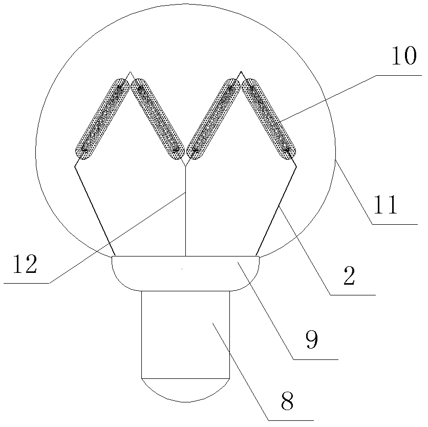
[0021] Such as figure 1 , image 3 with Figure 4 The shown LED light bulb includes a lamp holder 8, a lamp housing 9, at least two wires 2, a constant current power supply, a lampshade 11 and a plurality of LED light sources 10, the lamp housing 9 is installed on the lamp holder 8, and the lampshade 11 is installed on the lamp housing 9, the wire 2 is connected to the lamp holder 8 through a constant current power supply, and the wire 2 is used for connecting the LED light source 10 and the lamp holder 8 and also supports the LED light source 10. The LED light source 10 between the two wires 2 is located in the inner cavity of the lampshade 11, and the best position of the LED light source 10 is at the center of the inner cavity of the lampshade 11, which has high luminous efficiency.

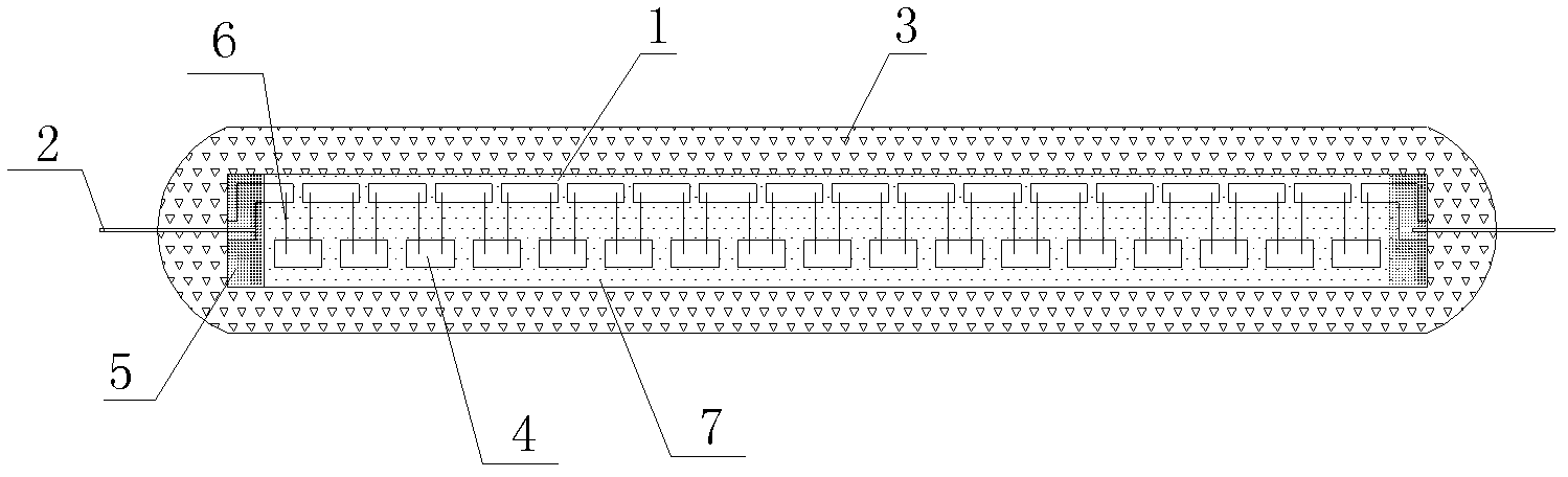
[0022] The LED light source is composed of chip 4, insulating glue 3, fluorescent powder 7, gold wire 6, wire 2, adhesive 5 and flexible PCB board 1. Phosphor powder 7 is coated on the chip...

Embodiment 2

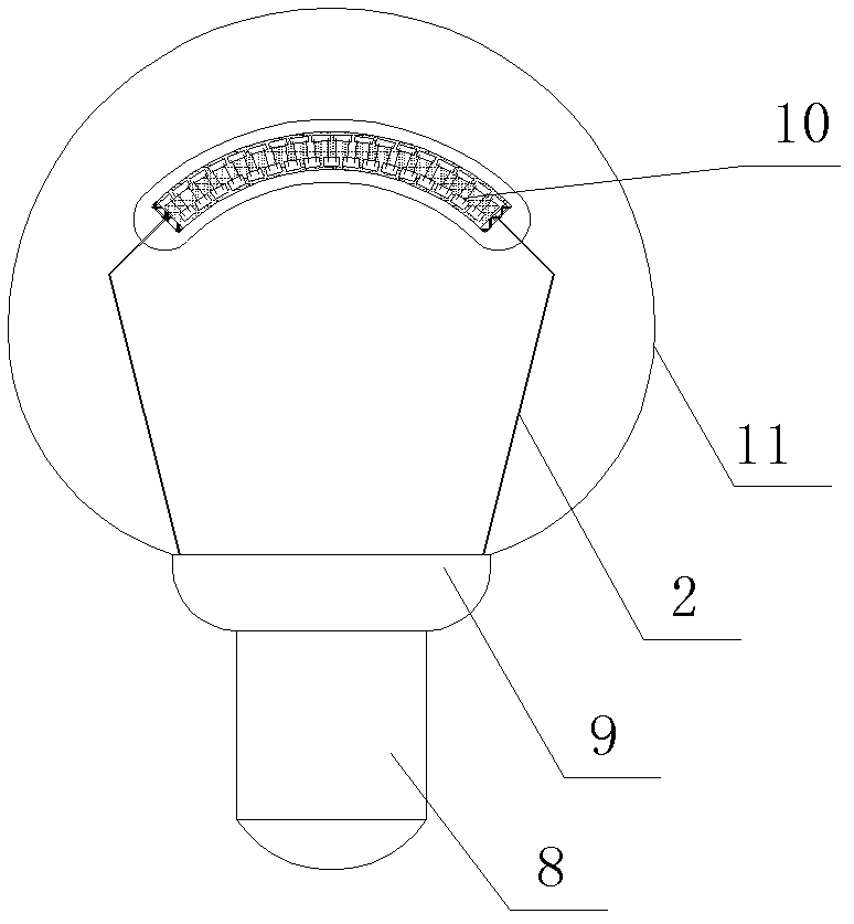
[0025] Such as figure 2 , image 3 with Figure 4 In the shown LED light bulb, except for the shape of the flexible PCB board 1 and the arrangement shape of the LED light sources 10, the number of the LED light sources 10 can be single or multiple, and the other structures are the same as those of the first embodiment.

[0026] The flexible PCB board 1 is bent in an arc shape, that is, the LED light source 10 is bent in an arc shape, which is convenient to be made into various shapes and improves luminous efficiency. Compared with Embodiment 1, where two adjacent LED light sources 10 are arranged in a V-shaped structure The number of light sources 10 used can be reduced. The flexible PCB 1 can be bent into an arc but cannot be used at an angle. After the angle is bent, the chip 4 on the flexible PCB 1 is likely to warp and cause the gold wire 6 to break, and the flexible PCB 1 is also easy to break.

[0027] The above-mentioned two embodiments are only preferred implementat...


PUM


Abstract

The invention relates to the field of illuminating lighting fixtures, and provides a light-emitting diode (LED) lamp bulb. The LED lamp bulb comprises a lamp cap, a lamp shell, a constant current power supply, at least two guide lines, a lampshade and an LED light source. The LED light source between the two guide lines is located in an inner cavity of the lampshade; the LED light source comprises a chip, fluorescent powder and a flexible printed circuit board (PCB); the flexible PCB is made of circuits printed on a polyimide or polyester film substrate and is in transparent or semitransparent shape, light transmittance of the flexible PCB is at least 40 %, and temperature resistance range of the flexible PCB is between minus 45 DEG C and 300 DEG C; and the diameter of the LED light source is within 1.5 millimeters. The LED lamp bulb has the advantages of being ingenious in structure, high in light using efficiency, and low in production cost.

Description

technical field [0001] The invention relates to the field of lighting fixtures, in particular to a light bulb with an LED as a light source. Background technique [0002] Energy shortage is a hot topic in today's world. In the lighting industry, LED bulbs are used to replace traditional incandescent lamps (tungsten lamps) with high energy consumption and short life due to their advantages such as high efficiency, energy saving, environmental protection, and long life. preferred. Incandescent lamp (tungsten filament lamp) includes: filament, filament support frame, transparent lampshade, filling gas and lamp cap. The filament support frame supports the filament. The transparent bulb is filled with inert gas and requires sealing. The efficiency is low and the process is complicated, and its benefit is 360-degree light emission. At present, there are LED bulbs similar to incandescent lamps on the market that emit nearly 360 degrees. The structure includes a lamp cap, a lamp h...

Claims


Application Information

Patent Timeline
Patent Type & Authority Applications(China)
IPC IPC(8): F21S2/00F21V19/00F21V23/06F21Y101/02F21K9/238F21Y115/10
Inventor 王元成王丽娜
Owner 宁波昊美电子科技有限公司
Why Eureka
Try Eureka