

Backlight module and display device
A backlight module and light source technology, which is applied to lighting devices, fixed lighting devices, components of lighting devices, etc., can solve the problems of reducing the utilization rate of light energy, weakening the Hotspot phenomenon, etc., so as to increase the utilization rate of light energy and improve the Hotspot phenomenon. phenomenon, the effect of improving the picture quality
- Summary
- Abstract
- Description
- Claims
- Application Information
AI Technical Summary
Problems solved by technology
Method used
Image

Examples
Embodiment 1
[0035] This embodiment provides a backlight module, which includes a light source, a light guide plate, and a light reflection structure. The light source is arranged on the side of the light guide plate; the light reflection structure is used to reflect the part of the light emitted by the light source that fails to enter the light guide plate to the light guide plate (preferably reflected to the dark area on the light guide plate).
[0036] It can be seen that the backlight module described in this embodiment can increase the utilization rate of light energy, and can further eliminate the Hotspot phenomenon.
[0037] The light reflection structure can preferably be arranged on the edge area of the light-emitting surface of the light guide plate adjacent to the light source, and is not in contact with the light guide plate, but deflects the light emitted by the adjacent light source to the light-emitting surface of the light guide plate. The light above is reflected back in...
Embodiment 2
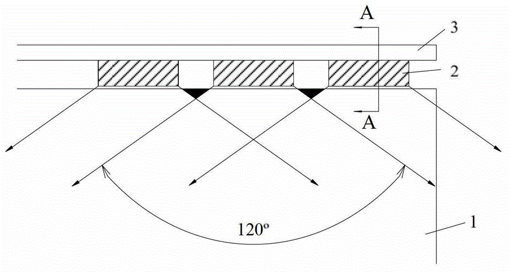
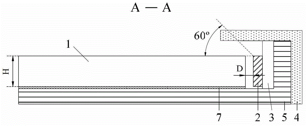
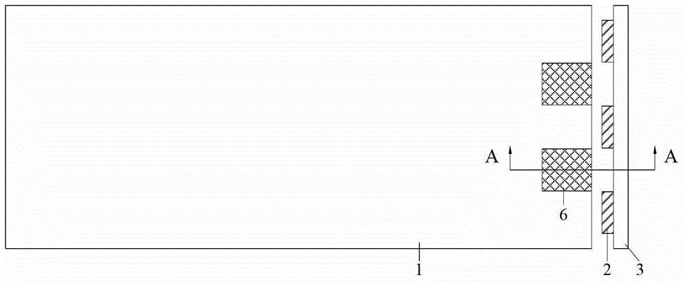
[0041] Such as image 3 , 4 As shown, this embodiment provides a backlight module, including a light source, a light guide plate 1 , a light reflection structure 6 , a back plate 5 and an outer frame 4 , and preferably also includes a reflection sheet 7 .
[0042] Wherein, the light source includes a plurality of sub-light sources 2 and a PCB board 3 arranged at the bottom of the plurality of sub-light sources 2, the plurality of sub-light sources 2 are arranged at intervals on the side of the light guide plate 1 and arranged in a straight line, and the plurality of sub-light sources 2 None of them are in contact with the light guide plate 1, so as to prevent the light guide plate from being heated and melted due to heat generation when the sub-light source is working.
[0043] Preferably, the sub-light source is a light emitting diode (LED, Light Emitting Diode) or an electroluminescent sheet (EL, electroliminescent).
[0044] The bottom of the light guide plate 1 is provid...
Embodiment 3
[0053] Such as Figure 5 As shown, the difference between the backlight module described in this embodiment and Embodiment 2 is:
[0054] One light reflection structure 6 is used, and the length of the light reflection structure 6 extends along the direction in which the plurality of sub-light sources are arranged, and the length is greater than the distance between the first and last two sub-light sources of the plurality of sub-light sources, so as to simplify the manufacturing process .
[0055] This embodiment also provides a display device including the above-mentioned backlight module.
[0056] Other structures and functions in this embodiment are the same as those in Embodiment 2, and will not be repeated here.
PUM
| Property | Measurement | Unit |
|---|---|---|
| Beam angle | aaaaa | aaaaa |
Abstract
Description
Claims
Application Information