Supercharge Your Innovation With Domain-Expert AI Agents!

Channel system

A channel and channel wall technology, applied in the field of channel systems, can solve the problems of no large-scale commercial applications, large pressure drop of deflectors, etc.

Active Publication Date: 2013-03-20
S·M·尼尔松
View PDF7 Cites 0 Cited by
  • Summary
  • Abstract
  • Description
  • Claims
  • Application Information

AI Technical Summary

Problems solved by technology

However, deflectors of the type described produce excessive pressure drops and are therefore not widely used commercially.

Method used


Image

  • Channel system
  • Channel system
  • Channel system

Examples


Embodiment Construction

[0036] In order to exemplify the current preferred embodiment, the present invention will be described in more detail below with reference to schematic diagrams.

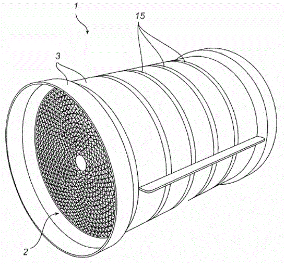
[0037] figure 1 A reel 1 with a channel system 2 according to the invention is exemplified. The drum 1 may be used for a catalytic converter in a heat exchanger such as a rotary heat exchanger, an air-cooled nuclear reactor, a gas turbine blade cooler or any other suitable device.

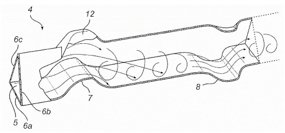
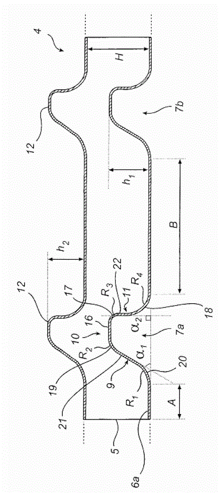
[0038] make up channel 4 (see Image 6 ) of corrugated strip (corrugated strip) 13 and at least one flat strip 14 rolled up to form a cylinder with the required diameter, which constitutes the actual core of the channel system 2 in the reel 1 . The serrations 15 in the corrugated belt 13 and the substantially planar flat belt 14 prevent the formed roll from collapsing. That is, the corrugated belt 13 and the flat belt 14 prevent the different layers of said belts 12 and 13 from being misaligned with each other. Furthermore, the casin...


PUM


Abstract

The invention relates to a channel system. The channel system is used for optimizing the relationship between the pressure decline of fluid flowing cross the system and heat, moisture and / or mass transfer. The channel system comprises at least one channel and at least one deflector, wherein the channel is provided with at least one channel wall, and the deflector has a preset height; the deflector laterally extends across the channel in the flowing direction of the fluid; the deflector comprises an upstream part, a downstream part and a middle part, the middle part is arranged between the upstream part and the downstream part, the upstream part deviates from the channel wall inward the channel in the flowing direction of the fluid, the downstream part returns back to the channel wall in the flowing direction of the fluid, and a transition between the middle part and the downstream part is bent by a preset radius (R3); a transition between the downstream part and the channel wall is bent by a preset radius (R4); and the radius (R4) of the transition between the downstream part and the channel wall is 0.2 times of the preset height of the deflector to 2 times of the preset height of the deflector.

Description

[0001] This application is a divisional application of a Chinese patent application with an application date of April 18, 2008, an application number of 200880128696.9, and a title of "channel system". technical field [0002] The invention relates to a channel system for optimizing the relationship between the pressure drop and the heat, moisture and / or mass transfer of a fluid flowing through the channel system, the channel system comprising at least one channel wall At least one channel and at least one flow director (flow director) having a predetermined height, the flow director extends transversely to the channel in the direction of fluid flow, the flow director includes an upstream portion, a downstream portion, and a flow director located at the an intermediate portion between the upstream portion and the downstream portion, the upstream portion deviates from the channel wall toward the interior of the channel in the fluid flow direction, and the downstream portion devi...

Claims


Application Information

Patent Timeline
IPC IPC(8): F28F13/08F01N3/28
Inventor S·M·尼尔松
Owner S·M·尼尔松
Features
  • R&D
  • Intellectual Property
  • Life Sciences
  • Materials
  • Tech Scout
  • Unparalleled Data Quality
  • Higher Quality Content
  • 60% Fewer Hallucinations
Learn More