Drive circuit and applicative piezoelectric actuating pump thereof

A drive circuit, piezoelectric actuation technology, applied in piezoelectric effect/electrostrictive or magnetostrictive motors, electrical components, generators/motors, etc. Inability to effectively reduce the size of the circuit board and other problems

Inactive Publication Date: 2013-03-20
MICROJET TECH
View PDF6 Cites 16 Cited by
  • Summary
  • Abstract
  • Description
  • Claims
  • Application Information

AI Technical Summary

Problems solved by technology

Although the known driving circuit 100 can indeed boost and convert the DC voltage into an AC voltage, the known driving circuit 100 is composed of three discrete circuit units, so that the size of this circuit design ca

Method used


Image

  • Drive circuit and applicative piezoelectric actuating pump thereof
  • Drive circuit and applicative piezoelectric actuating pump thereof
  • Drive circuit and applicative piezoelectric actuating pump thereof

Examples


Embodiment Construction

[0045] A typical embodiment embodying the features and advantages of the present invention will be described in detail in the description in the following paragraphs. It should be understood that the present invention is capable of various changes in different aspects without departing from the scope of the present invention, and that the description and drawings are illustrative in nature rather than limiting the present invention.

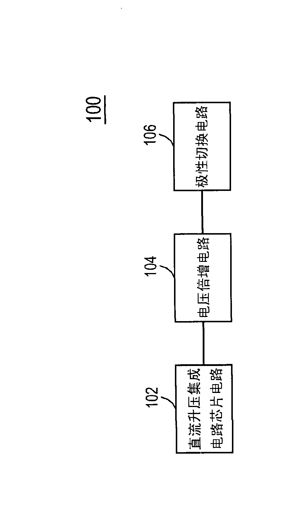
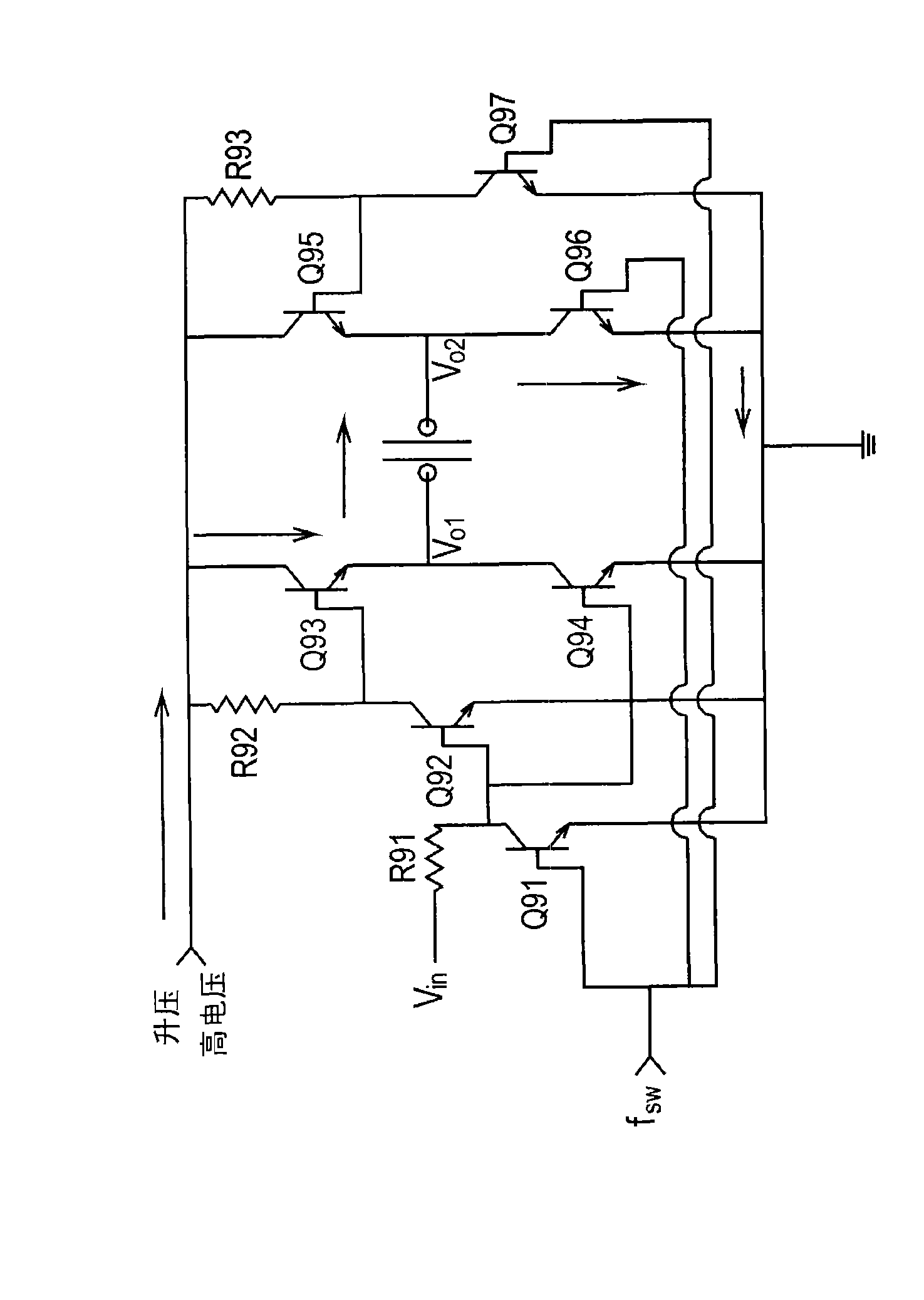
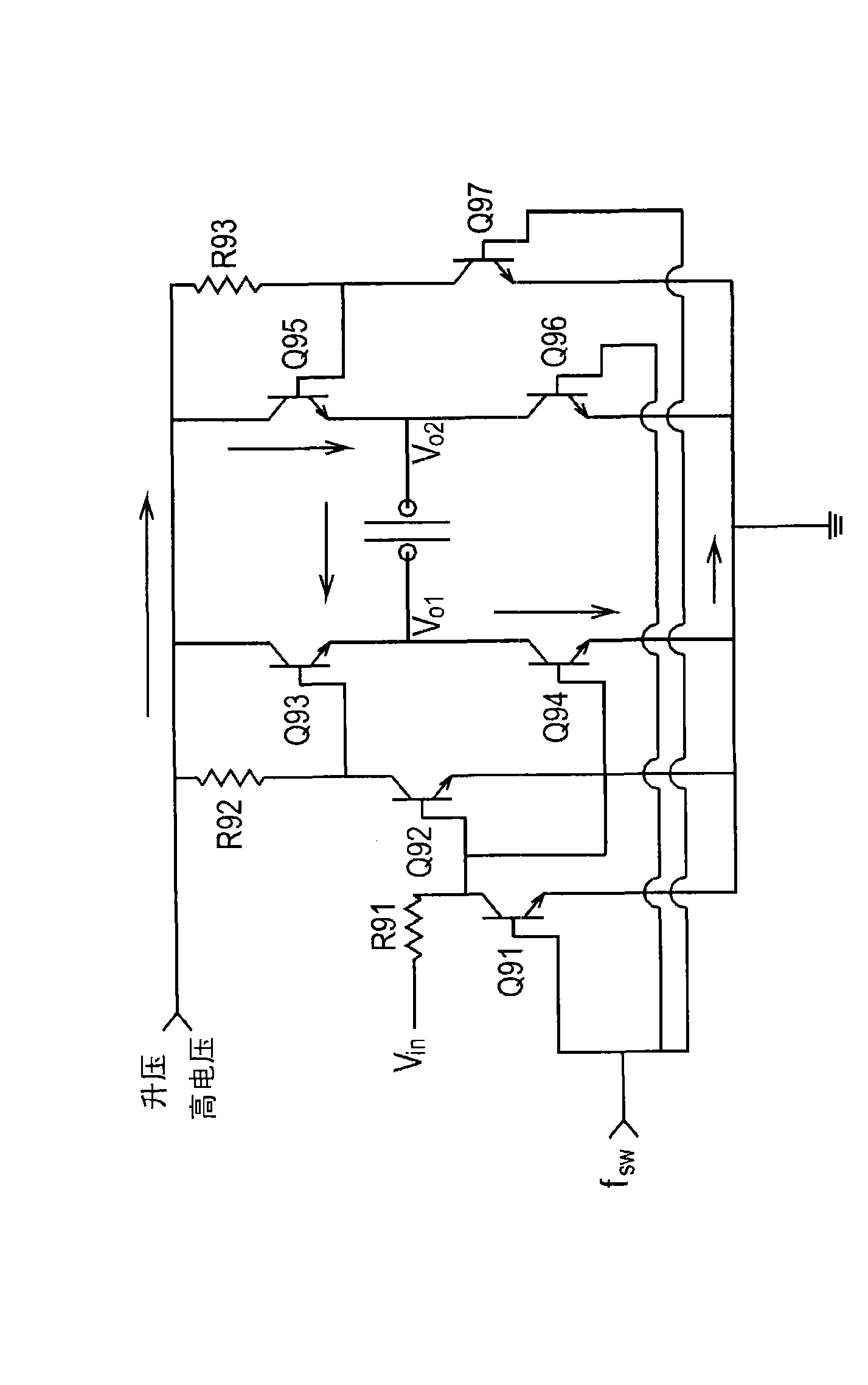
[0046] see Figure 3A , which is a structural schematic diagram of a piezoelectric actuated pump in a preferred embodiment of the present invention. As shown in the figure, the piezoelectric actuated pump 3 of the present invention is mainly composed of a mechanism body 301 and a drive circuit 300. The drive circuit 300 and the mechanism The main body 301 is connected to mainly use the electric driving circuit 300 to receive an input DC low voltage and convert it into output AC voltages Vo1 and Vo2 to drive the mechanism main body 301 to operate....


PUM

PropertyMeasurementUnit
Capacitanceaaaaaaaaaa

Abstract

The invention provides a drive circuit applicable to a piezoelectric actuating pump. The piezoelectric actuating pump is provided with a piezoelectric actuator. The drive circuit is provided with a boosted circuit unit and a boosted propelling integrated circuit. The boosted circuit unit at least comprises a plurality of capacitors, a plurality of resistors and a boosted integrated circuit chip which is connected with the plurality of capacitors and the plurality of resistors. The boosted propelling integrated circuit is used for boosting voltage values of input voltage and converting polarity of the input voltage. Therefore, the output voltage is produced to drive the piezoelectric actuator so as to convert electric energy to mechanical energy.

Description

technical field [0001] The present invention relates to a driving circuit, in particular to a driving circuit suitable for piezoelectric actuation pumps and capable of converting electrical energy into mechanical energy and the applicable piezoelectric actuation pumps. Background technique [0002] A typical inkjet printer includes a piezo-actuated pump to eject ink droplets via its periodic high-speed motion. Piezoelectrically actuated pumps usually require a high-voltage AC voltage to act on them to drive the piezoelectric actuator to perform periodic high-speed motion. Using high-voltage AC voltage to drive the piezoelectric actuator, the piezoelectric actuator can output periodic control signals to the single-hole inkjet or porous inkjet vibrating piece to drive the single-hole inkjet vibrating piece or porous inkjet vibration The sheet undergoes periodic motion whereby ink droplets are ejected through a single or multi-hole nozzle of an inkjet printer. Therefore, piez...

Claims


Application Information

Patent Timeline
IPC IPC(8): H02M9/04H02N2/06
Inventor 陈世昌张英伦
Owner MICROJET TECH
Why Eureka
Try Eureka